Preface:
Here provides an easy introduction of How to set up of nRF52840 & nRF52833 Module Demo board MDBT50Q-DB-40 (for nRF52840) & MDBT50Q-DB-33 (for nRF52833)
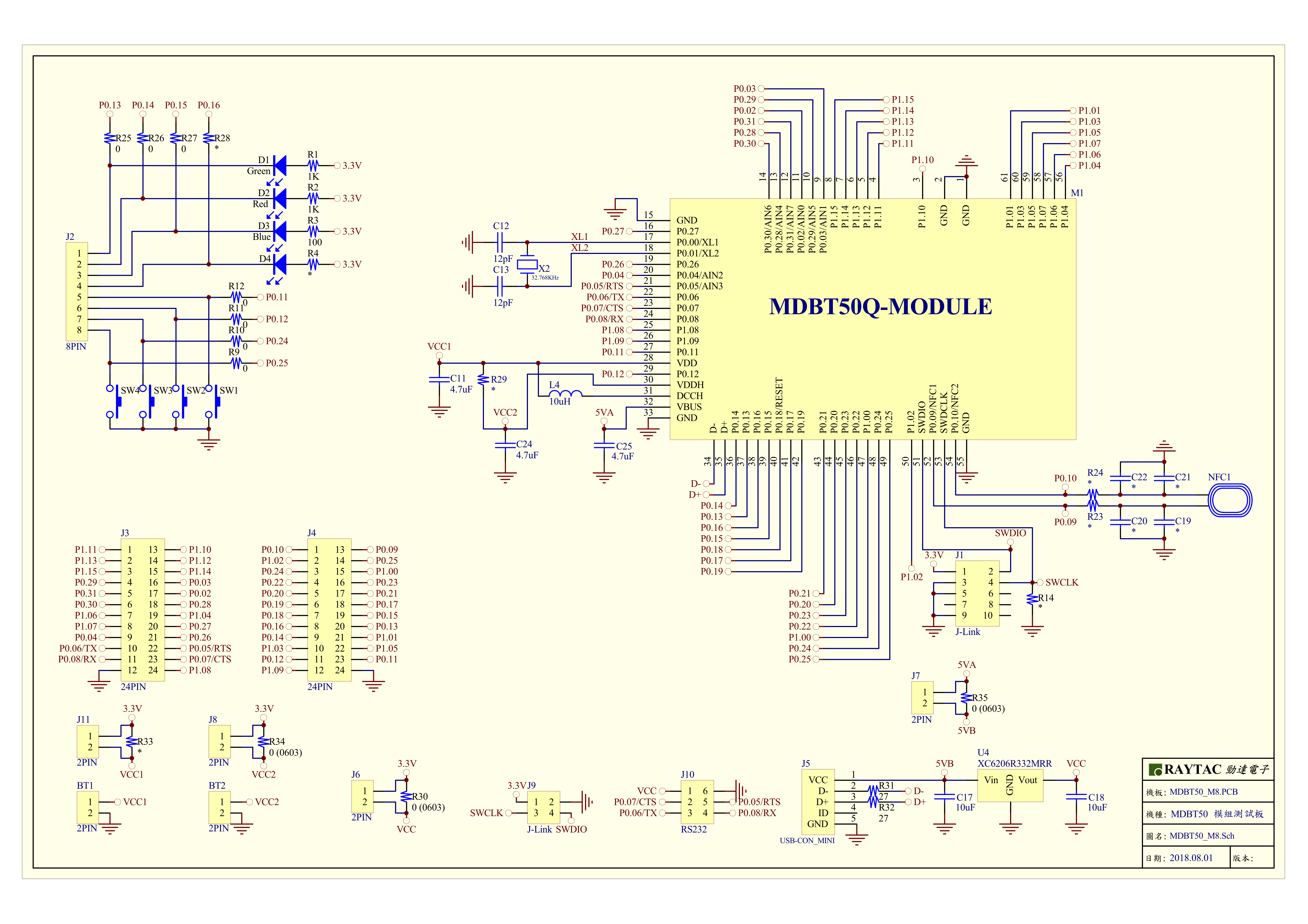
MDBT50Q-DB-40 is a Demo Board built by Raytac’s
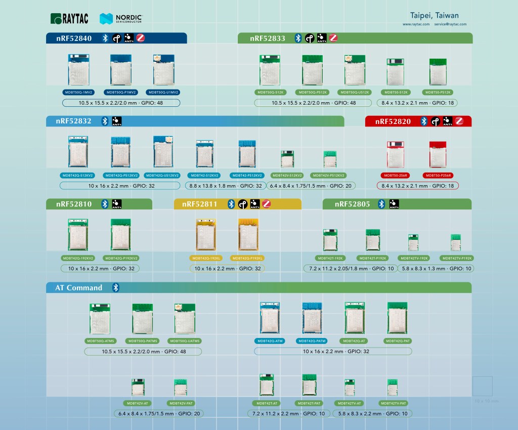
MDBT50Q-1MV2 with Red PCBA deployed nRF52840 SoC with Bluetooth 5 & Thread Combo, with 1MB Flash Memory and 256KB RAM and Chip Antenna.
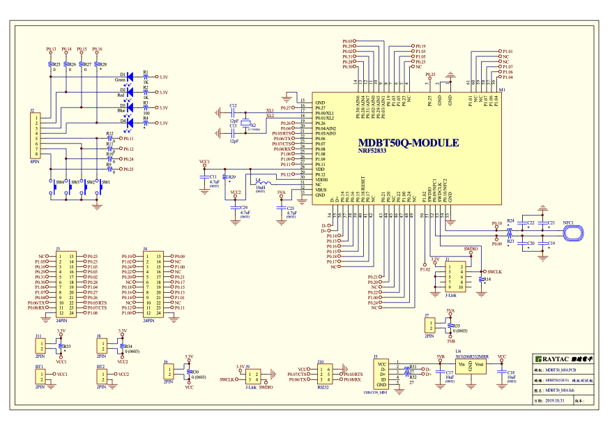
MDBT50Q-DB-33 is a Demo Board built by Raytac’s
MDBT50Q-512K with Green PCBA deployed nRF52833 SoC with Bluetooth 5 & Thread Combo, with 512KB Flash Memory and 128KB RAM and Chip Antenna.
Both demo boards are Bluetooth BT5.4 qualified and FCC, IC, CE, Telec, KC, SRRC, RCM, NCC, WPC pre-certified.
Table of contents:
1.1 Hardware Set Up
1.2 Software Kits resources & preparations
1.3 Flash the ready firmware into Raytac’s module
1.4 DFU to MDBT50Q-DB-XX through USB interface
1.1 Hardware Set Up
MDBT50Q-DB-XX package contains:
- 1 x MDBT50Q-DB-40/MDBT50Q-DB-33
- 1 x IDC Wire
- 1 x Data/Power Mini USB Wire(for data transferring)
Where to buy MDBT50Q-DB-XX?
MDBT50Q-DB-40 (nRF52840 Solution)
MDBT50Q-DB-33 (nRF52833 Solution)
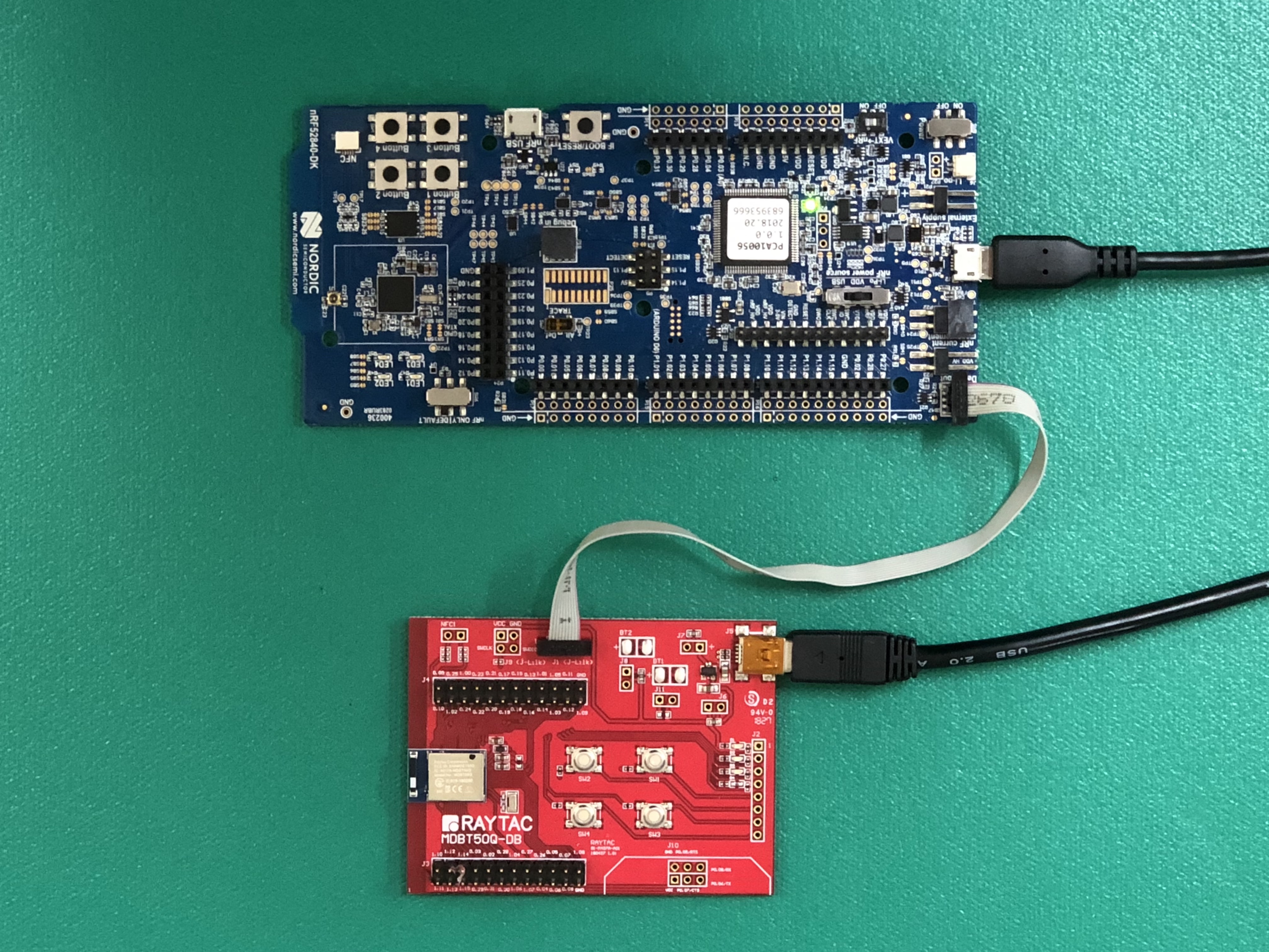
→ Connect Nordic NRF52-DK/NRF52840-DK Connect with MDBT50Q-DB-40 by IDC Wire
※Note: PCA10056 (NRF52840-DK) / PCA10040 (NRF52832-DK) / PCA10100(NRF52833-DK)
→ Power up MDBT50Q-DB-XX using Mini USB
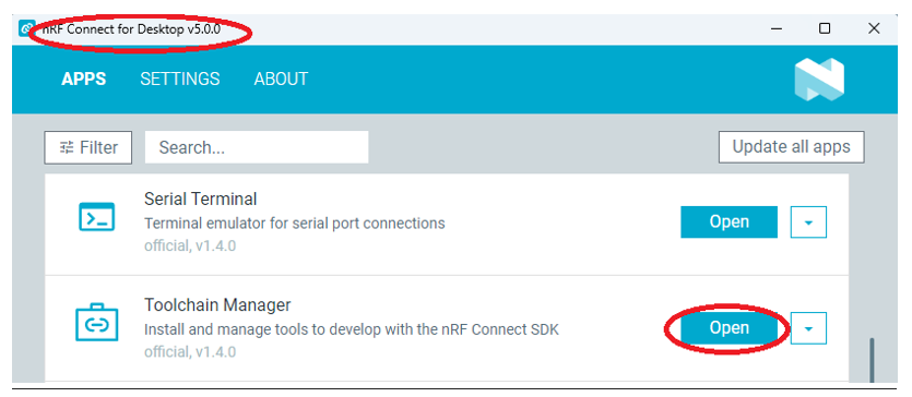
2A. Find “Toolchain Manager” in app nRFConnect for Desktop
2B. Install nRFConnect SDK V2.6.0 to your working site.

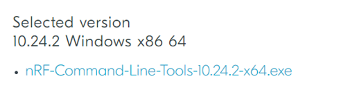
2C. Prepared with the latest version of nRF Command Line Tools
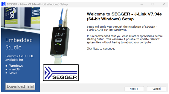
**Note: SEGGER J-LINK Upgrade message might pop up while you’re doing above download.
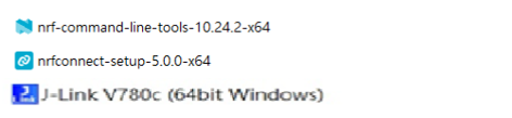
2D. Locate all the necessary kits for programming in PC
1.3 Flash the ready firmware into Raytac’s module
Intro:
With the ready built code of zephyr.hex (Made through NCS) or nrf52840_xxaa.hex & s140_nrf52_7.2.0_softdevice.hex (Made through nRF5-SDK) file for application, we would like to move onto flashing code into the MDBT50Q BLE module(mounted on MDBT50Q-DB-XX demo board).
Step1.
Execute nRF Connect >> Programmer > > Open

Step2.
Click “SELECT DEVICE” >> Find icon “nRF52840 DK” which is detected by the programmer app
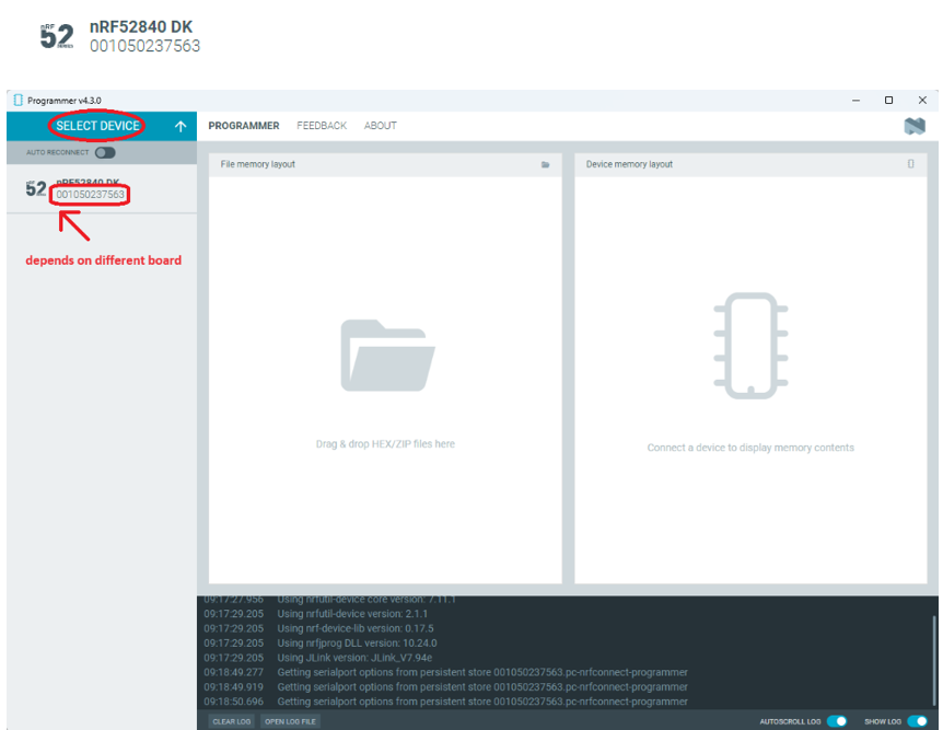
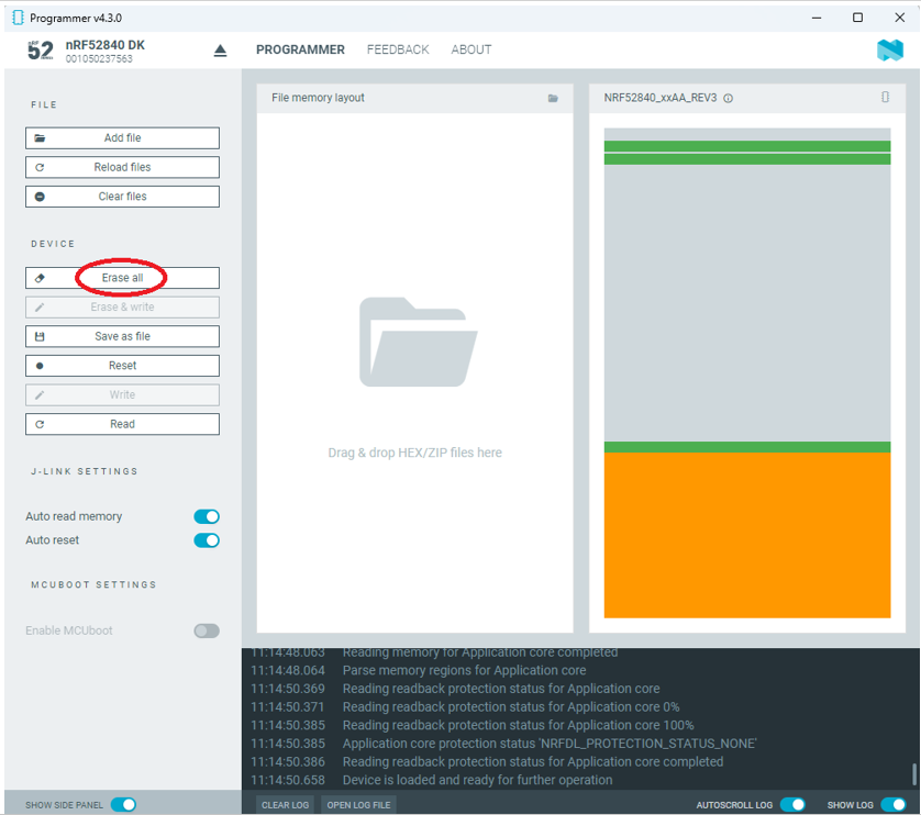
Step3.
Click “nRF52840 DK”>> “Erase All” to remove flash memory inside MDBT50Q BLE Module
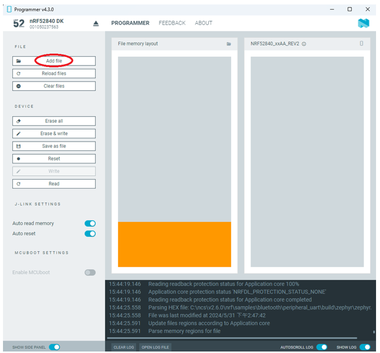
Step4.
Click “Add File” to load application zephyr.hex into programmer
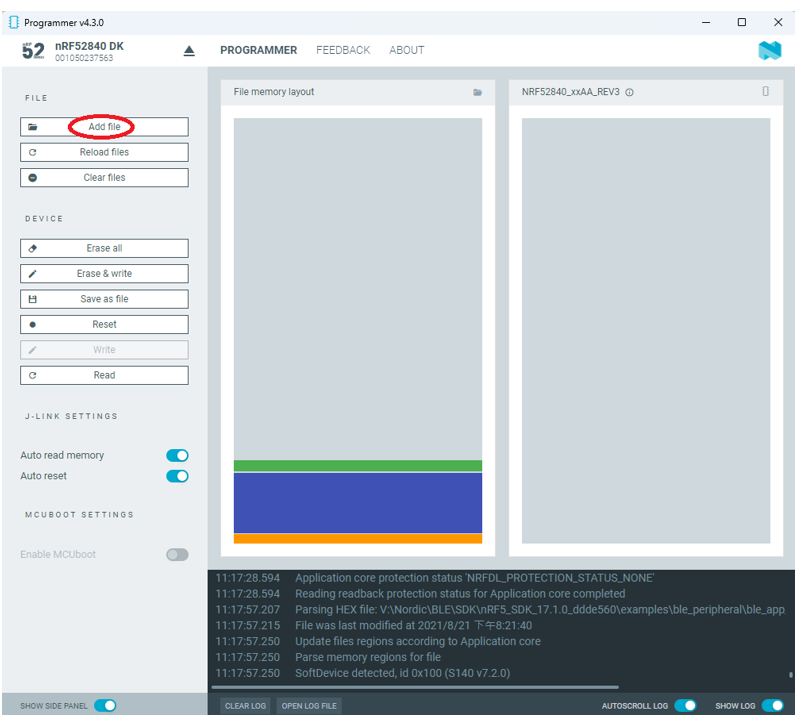
✓ If you’re using nRF Connect SDK for code compiling as above, Program the hex file to MDBT50Q BLE module on the MDBT50Q-DB Demo board:
C:\ncs\v2.6.0\nrf\samples\bluetooth\peripheral_uart\build\zephyr\zephyr.hex
✓ If you’re using NRF5 SDK for code compiling, you need to program the following two hex files into the MDBT50Q BLE module on the demo board:
nRF5_SDK_17.1.0_ddde560\components\softdevice\s140\hex\s140_nrf52_7.2.0_softdevice.hex
nRF5_SDK_17.1.0_ddde560\examples\ble_peripheral\ble_app_uart\pca10056\s140\arm5_no_packs\_build\ nrf52840_xxaa.hex
!! Important Tips to securing DFU:!!
✓ If it is confirmed to require DFU in this project, it is recommended to build a 4-in-1 bootloader. (The 4-in-1 bootloader should be created by your own after having the private key activated uniquely).
(1) bootloader.hex
(2) bootloader_setting_file.hex
(3) s140_nrf52_7.2.0_softdevice.hex
(4) nrf52840_xxaa.hex
1.4 DFU to MDBT50Q-DB-XX through USB interface
Intro : Before DFU implement , Please make sure the bootloader file has been installed in your MDBT50Q BLE module.
※Note: NRF52840 SoC supports USB interface to utilize Device Firmware Update (DFU).
How do I prepare the software??
- Download nrfutil.exe file from Nordic website .
- It is workable to do List, Program, Recover, Erase, and operations with nRFutil device command to Nordic device.
- Open DOS mode to install device command type: nrfutil install device

How do I setup the hardware??
- Press Switch 4 and hold
- Power up Demo Board
- Blue LED Lights on
- Demo Board successfully enters into USB DFU Mode

How do I prepare the firmware??
**USB DFU works only in DOS mode.
**USB DFU only works when USB Bootloader installed in current loaded firmware (inside BLE Module)
A single, merged 4-in-1 hex file is required, which includes:
Bootloader, Bootloader setting, Softdevice, and Application.
Firmware DFU requires a .zip file.
USB DFU Execution Steps:
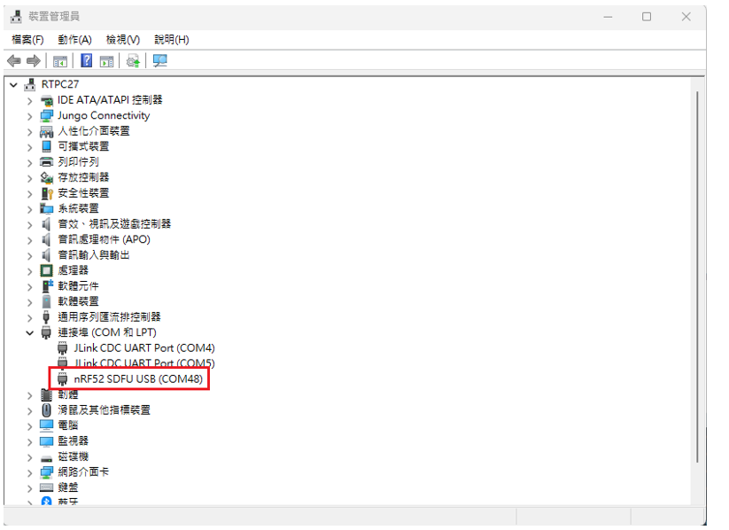
Step 1. When Blue LED Lights on with MDBT50Q-DB (Ready to enter USB DFU Mode)
Step 2. Find out Com Port No. “nRF52 SDFU USB(COMxx)”
Step 3. Execute USB DFU
Option 1. Using device program command:
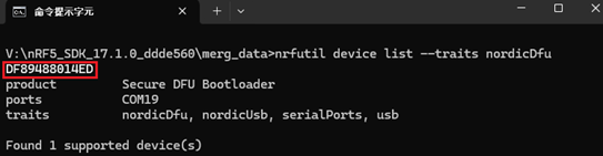
(1) List the devices with a DFU trigger interface by running:
nrfutil device list –traits nordicDfu
(2) Program new firmware to a device identified by its serial number by running:
nrfutil device program –firmware .zip nrf52840_xxaa.zip –serial-number XXXXXXXXXXXX

繼續閱覽 “How To Use nRF52840/nRF52833 module DevKit(MDBT50Q series) – 2024 Update – Applied to nRF5 SDK & nRF Connect SDK"


 Now we know


_1000X1000_190102")