As COMPUTEX 2026 approaches, are you ready to witness the next breakthrough in wireless connectivity technology?
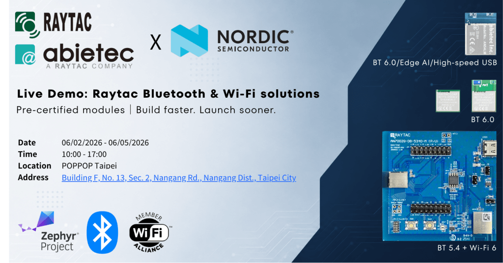
From June 2 to June 5, 2026, Raytac and abietec sincerely invite customers and partners worldwide to visit our exclusive booth at:
POPPOP Taipei (Taipei Bottle Cap Factory), Building F (Click here for Google Maps location)
Join us to explore the future of Bluetooth and Wi-Fi technologies, exchange ideas with our engineering team, and discover how next-generation wireless solutions can accelerate your product development.
Why Raytac/abietec?
We understand that having a powerful Nordic Semiconductor SoC is only the beginning of successful product development.
The real challenges often come afterward — including RF design optimization, antenna tuning, impedance matching, and complex global RF certifications.
At Raytac, we provide more than high-quality wireless modules; we help shorten your development cycle.
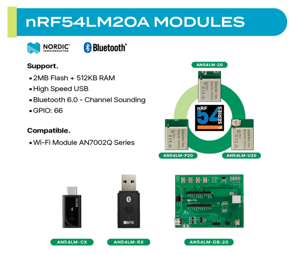
Industry-Leading Bluetooth® & WiFi Solutions
Built on Nordic Semiconductor’s advanced SoC platforms, Raytac modules deliver:
– Ultra-low power consumption
– Stable wireless performance
One-Stop Wireless Development Support
We understand the complexity behind RF engineering. Raytac’s solutions help reduce engineering effort in areas such as:
– Antenna design
– RF tuning & impedance matching
– Certification preparation
– Hardware integration
Allowing your engineering team to focus more on developing core product functionality.
A Truly Non-China Supply Chain
Raytac takes pride in maintaining a 100% non-China manufacturing background, offering greater supply chain transparency, flexibility, and competitiveness in international markets: an increasingly important advantage in today’s global environment.
Daily Tech Talks During the Event
Throughout the 4-day exhibition period, we will host daily Tech Talk sessions from 11:00 AM – 11:30 AM, covering:
– Nordic nRF54 and nRF70 series technologies
– Raytac’s Low-power Wi-Fi + Bluetooth® solutions
– Real-world application examples from customers
– How Raytac’s pre-certified modules help you shorten IoT development and reduce time-to-market
Whether you are looking for a reliable Bluetooth module, evaluating Wi-Fi solutions, or facing engineering challenges during product development, we welcome you to stop by and discuss your project with us — we may have ideas that help solve your challenges.
Reserve a Meeting with Us
Interested in scheduling an on-site discussion or learning more?
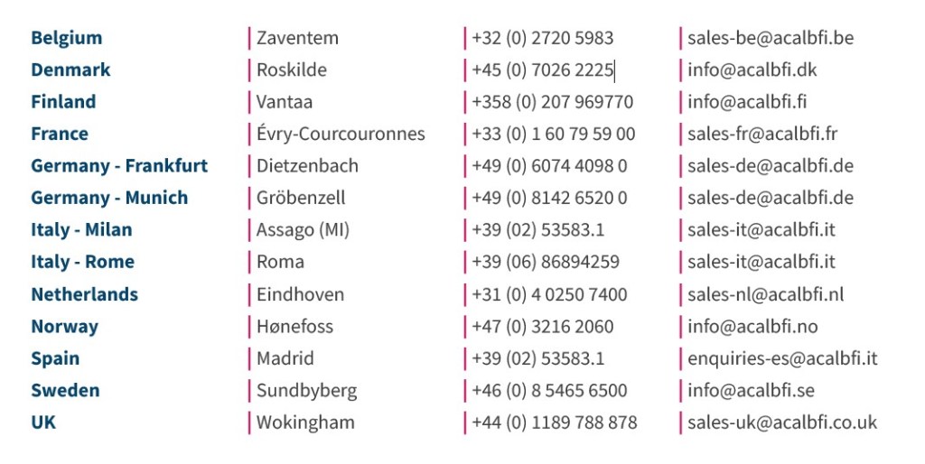
Please feel free to contact us directly on: https://www.raytac.com/contact/,
or reach out to our sales representative:
Mr. Welson Kuo
Email: welson@raytac.com
We look forward to seeing you in Nangang, Taipei.
Event Information
| Date: | June 2 (Tue) – June 5 (Fri), 2026 |
| Time: | 10:00 AM – 5:00 PM |
| Venue: | POPPOP Taipei(南港瓶蓋工廠), Building F |
| Address: | Building F, No. 13, Section 2, Nangang Road, Nangang District, Taipei City (Click here for Google Maps location) |
Edited by Business Development Manager: Welson Kuo
Raytac Corporation 勁達國際電子股份有限公司 / Raytac Corporation (USA) / abietec Inc.
A Bluetooth, Wi-Fi, and LoRa Module Maker/ODM & OEM Manufacturer based on
Nordic nRF54; nRF53: nRF52; nRF51; nRF7002
Infineon: CYW55912
NXP: RW610, RW612
Semtech: SX1262
Bluetooth Specification: BT6 ; BT5.4 ; BT5.3 ; BT5.2.
Wi-Fi Specification: Wi-Fi 6
LoRa Specification: LoRaWAN
Zephyr Project Silver Member
All products are FCC/IC/CE/Telec/KC/RCM/SRRC/NCC/WPC/RoHS/Reach Pre-Certified.
http://www.raytac.com
https://www.raytac.com/contact/
email: sales@raytac.com
Tel: +886-2-3234-0208(TW)/+1-626-328-3827(USA)