Raytac Group, a worldwide leader in wireless modules, wireless solutions, and a Nordic-recommended third-party module manufacturer, is pleased to announce the official release of the AN54LQ-AT and AN54LV-AT series, our newest Bluetooth® Low Energy AT Command modules built upon Nordic Semiconductor’s nRF54L15 ultra-low-power wireless SoC.
Designed for engineers who want to integrate BLE quickly and easily, the AT Command series comes with pre-loaded peripheral (slave) role firmware, enabling straightforward UART communication with a host MCU through simple AT Commands. Built on Nordic’s next-generation nRF54L15 SoC, the series delivers exceptional power efficiency, reducing power consumption by approximately 50% compared to previous-generation nRF52-based AT Command modules.
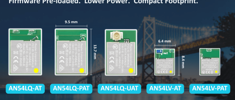
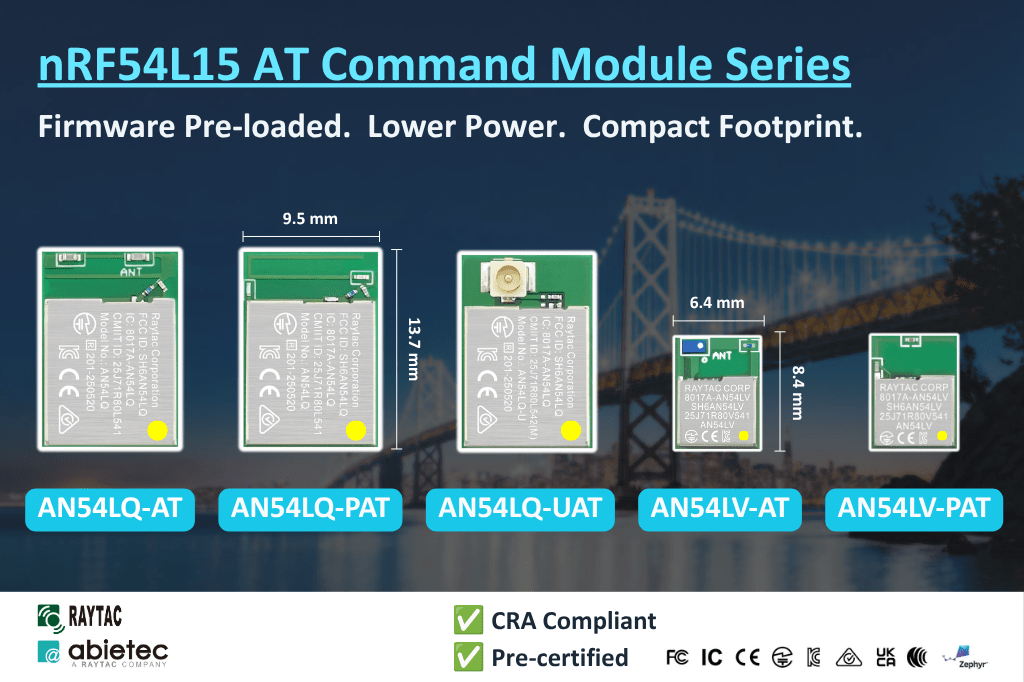
The nRF54L15 AT Command family is available in five variants to satisfy different RF and mechanical requirements.
The standard AN54LQ family measures only 9.5 × 13.7 × 1.8 mm, while the AN54LV family further reduces the footprint to just 6.4 × 8.4 × 1.5 mm, making it an excellent choice for wearable devices, portable products, industrial sensors, medical devices, and other space-constrained applications.
Engineers can integrate Bluetooth communication(peripheral role) into an existing MCU platform without implementing the Bluetooth LE protocol or maintaining a Bluetooth LE firmware stack.
Acting as a seamless bridge between the host MCU and Bluetooth devices, the AT Command module enables easy wireless communication without any complexity of firmware development.
Want to get started quickly with Raytac’s AN54LV-15 module? We provide a simple tutorial to guide you step-by-step through setting up the development and programming environment for the nRF54L15 module Development Board (AN54LV-DB-15) and nRF54L15-DK.
Table of Contents 1. Hardware Environment Setup 2. Software Development Kit Resources and Environment Setup 3. Software/Firmware Application Development 4. Flashing / Programming
1 x AN54LV-DB-15 (Raytac nRF54L15 module Development Board)
1 x IDC Ribbon Cable
2 x USB Type-C Connection Cables
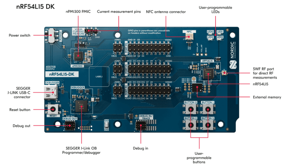
* Reminder: The “Nordic nRF54L15-DK" and “Raytac AN54LV-DB-15 Development Board" must be used together to proceed with application development and flashing firmware into the Raytac AN54LV-DB-15 development board.
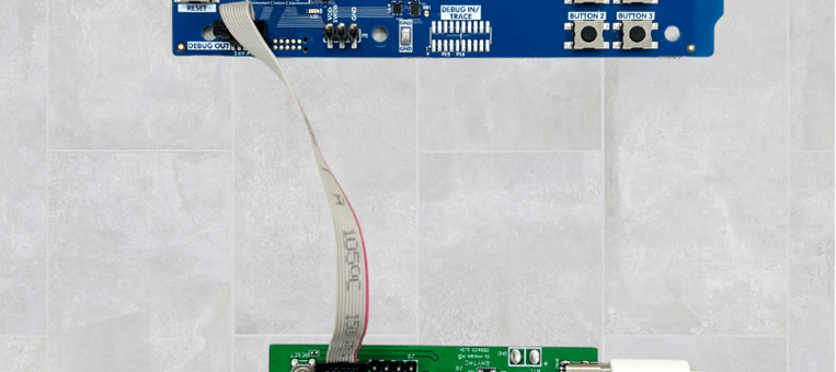
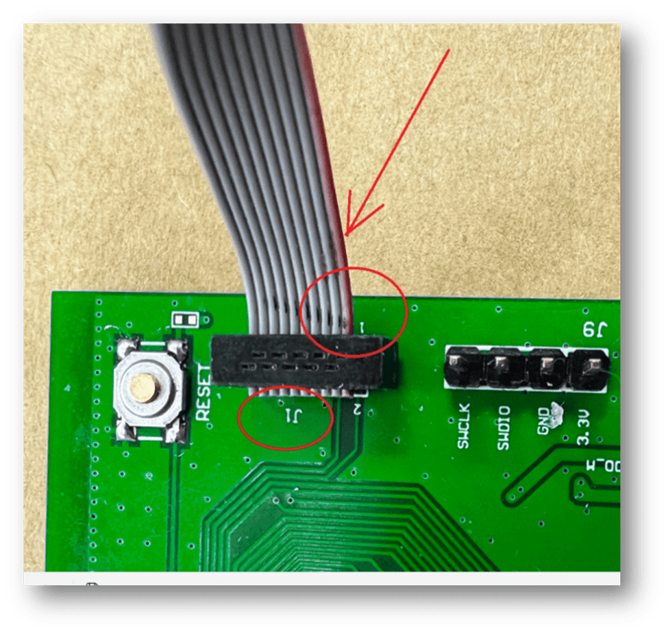
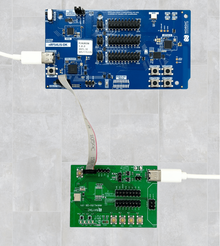
Setup Steps: Step 1: Connect the J-Link on the Nordic DK with the AN54LV-DB-15 using the IDC ribbon cable.
Make sure to match the red side of the IDC ribbon cable with “1″ printed on the AN54LV-DB-15’s J-Link socket.
Step 2: Use the Type-C USB cables to supply power to both the nRF54L15-DK and the AN54LV-DB-15.
The outcome should be same as the picture above.
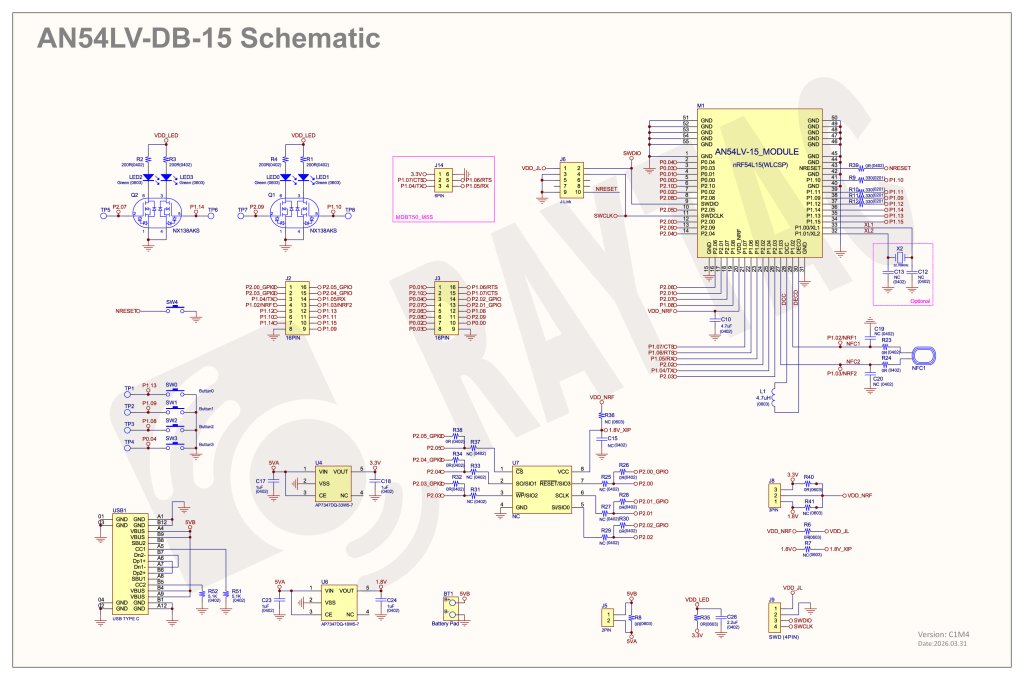
Step 3: AN54LV-DB-15 Schematic(Click on the schematic to zoom in):
Setup Steps: Step 1: Download the latest version of nRF Connect for Desktop. Choose the Windows 64-bit – version 5.3.1 installer (nrfconnect-setup-5.3.1-x64.exe). Once finished, you will see " nRF Connect for Desktop" on your PC.
Step 2: Download the latest version of nRF Command Line Tools. Choose the Windows X86 64 – version 10.24.2 installer (nrf-command-line-tools-10.24.2-x64.exe)
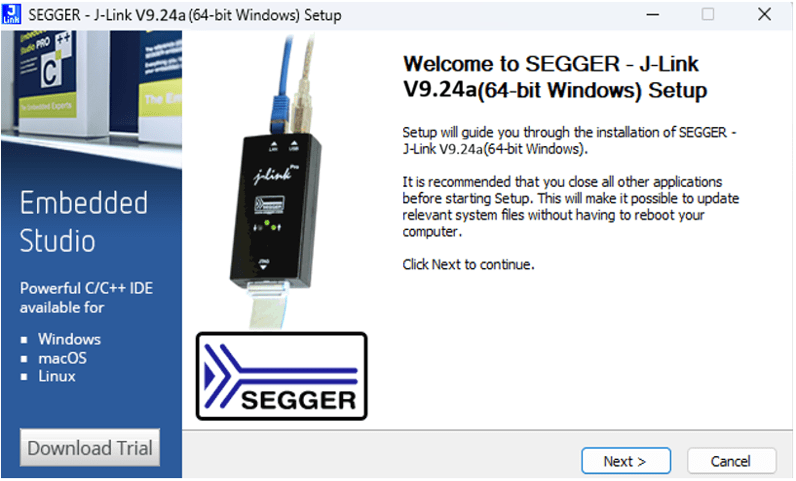
* Reminder: During the installation of the above two programs, a window may pop up prompting that SEGGER J-LINK needs to be installed or updated concurrently.
Step 3: Download the latest version of Visual Studio Code (VS Code). Choose Windows VSCodeUserSetup-x64 version 1.122 (VSCodeUserSetup-x64-1.122.1.exe). Once complete, you will see “Visual Studio Code" on your PC.
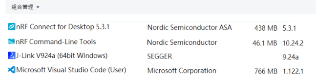
Step 4: After installation is complete, you can verify the installed packages in your PC’s Control Panel under “Programs and Features":
3. Software/Firmware Application Development You can develop application programs within the VS Code IDE development environment. Below steps are how to install and select your target SDK version (nRF Connect SDK v3.3.0 in this article):
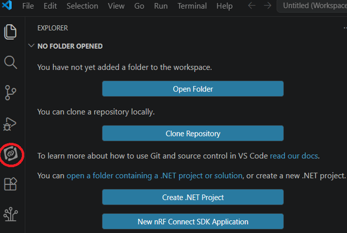
Step 1: Launch “VS Code"-> Select “nRF Connect" icon/extension on the side menu.
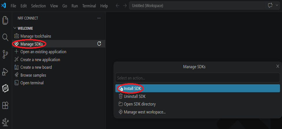
Click “Manage SDKs" and then select “Install SDK".
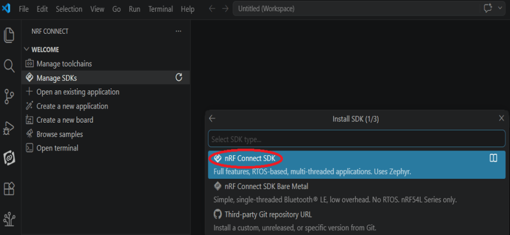
Step 2: Select “nRF Connect SDK".
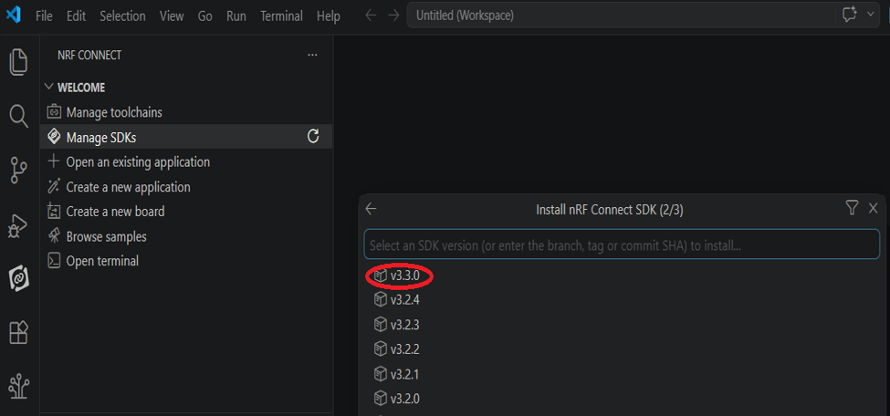
Step 3: You will see several available versions of nRF Connect SDK vx.x.x. It is highly recommended to choose and install NCS v3.3.0 or later. In this guide, we select nRF Connect SDK(NCS) v3.3.0.
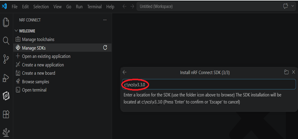
Step 4: Before starting the download for (NCS)v3.3.0, confirm your preferred target installation pathway. By default, it is configured to c:\ncs\v3.3.0. Press ‘Enter’ to confirm.
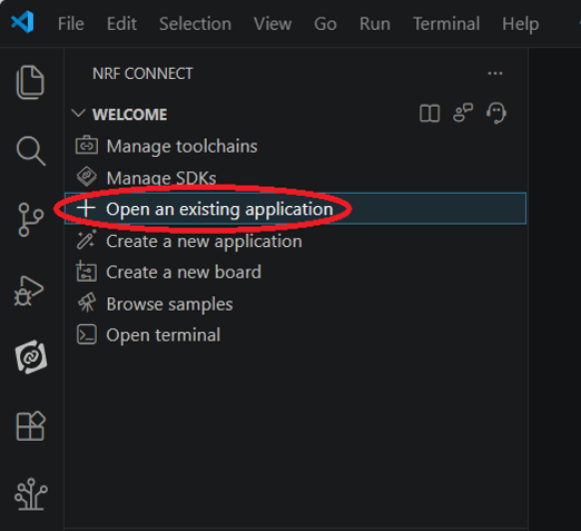
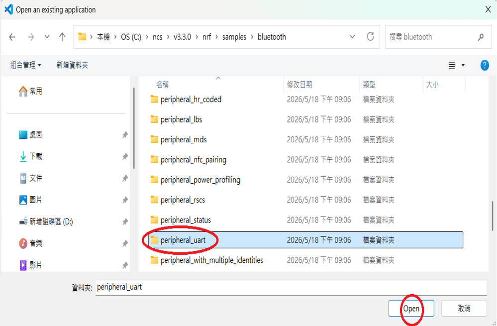
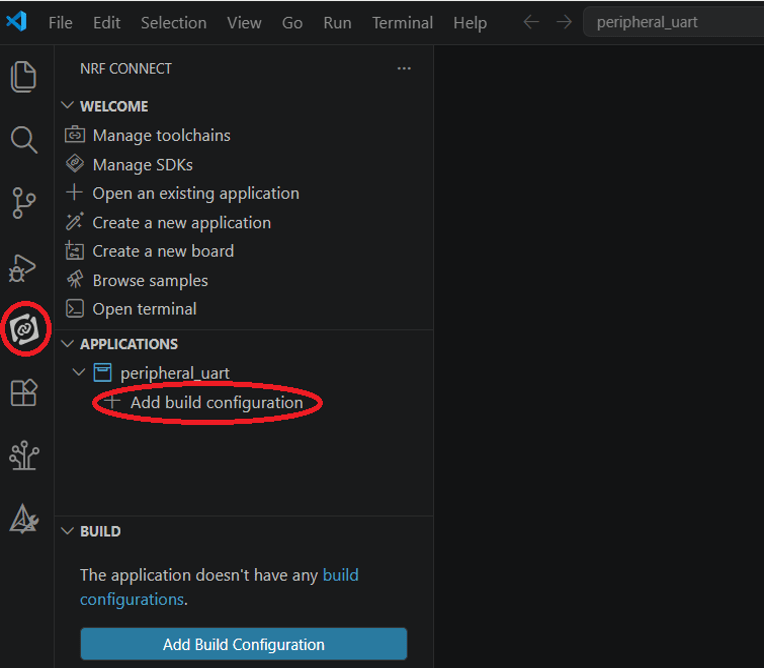
Step 5: Once the nRF Connect SDK v3.3.0 environment setup finishes successfully, open the Bluetooth sample folder and select the “peripheral_uart" application template, then click “Open".
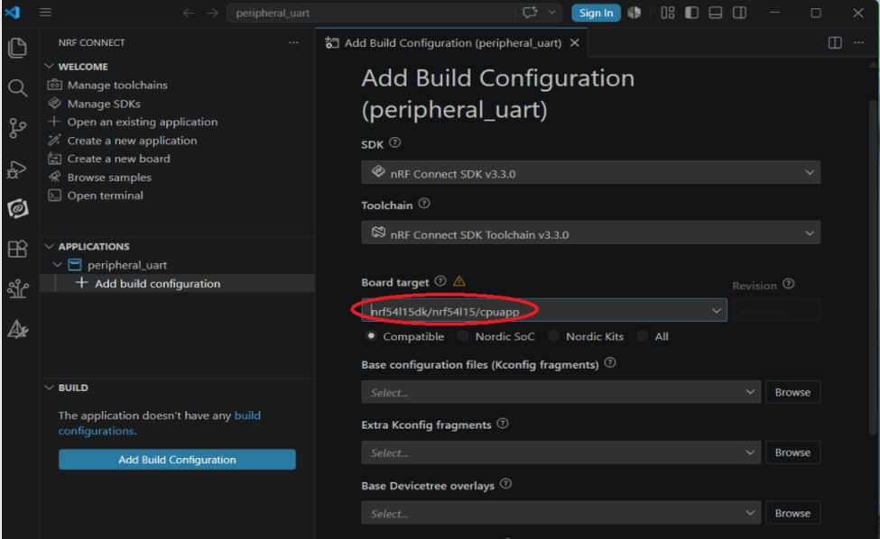
Step 6: In the “nRF Connect" layout, go to “Applications" –> “Add build configuration".
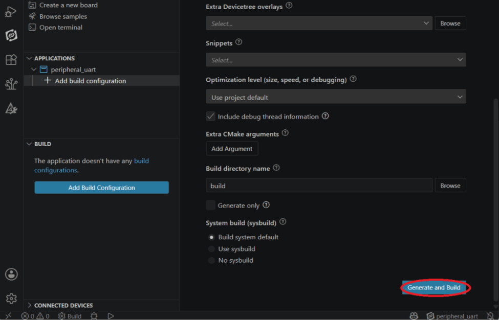
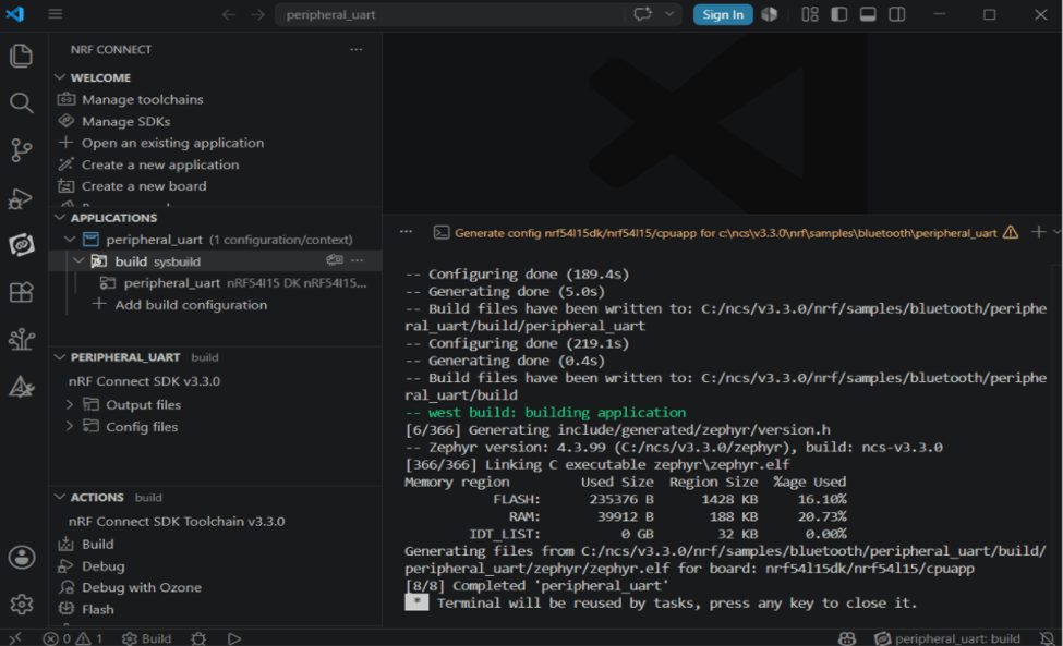
Under “Board target", look up and select “nrf54l15dk/nrf54l15/cpuapp" –> “Generate and Build".
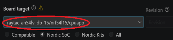
* Note: You can also choose the board name “raytac_an54lv_db_15/nrf54l15/cpuapp” for subsequent building and development.
After completing the configuration, you will see “Build complete".
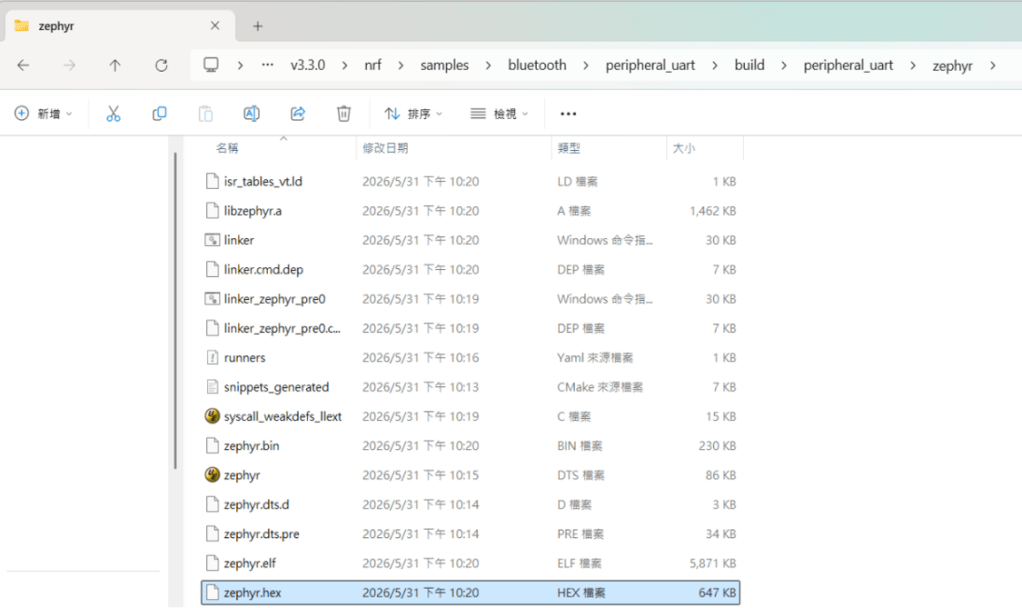
Step 7: Compilation completed. Once completed, a binary file named “zephyr.hex" will be generated in your “build" directory.
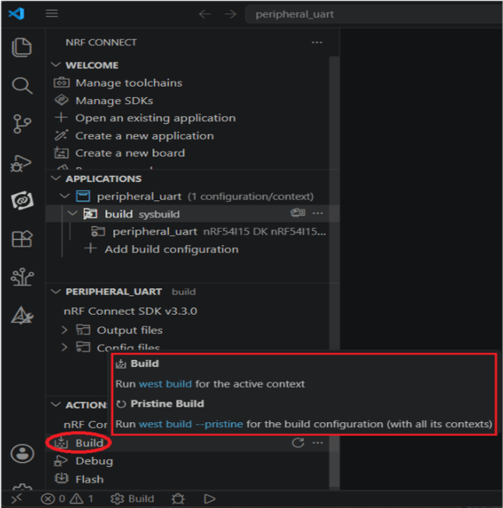
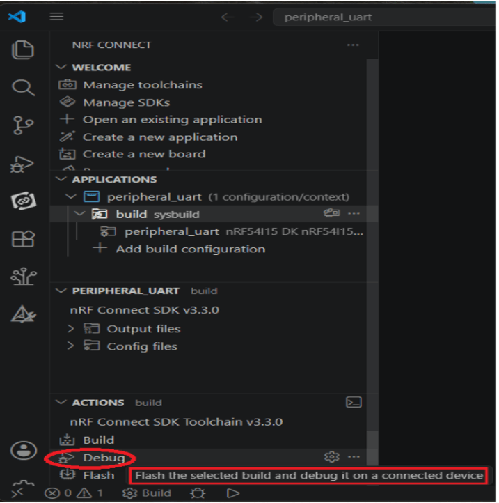
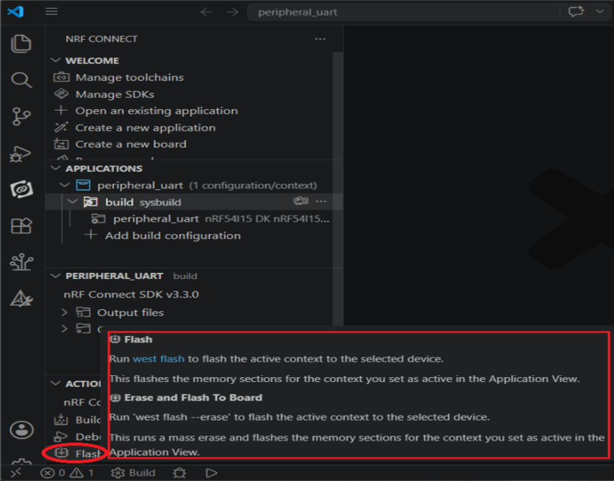
Step 8: Under the “ACTIONS" interface, you can switch between Build, Debug, and Flash functionalities dynamically.
Build
Debug
Flash
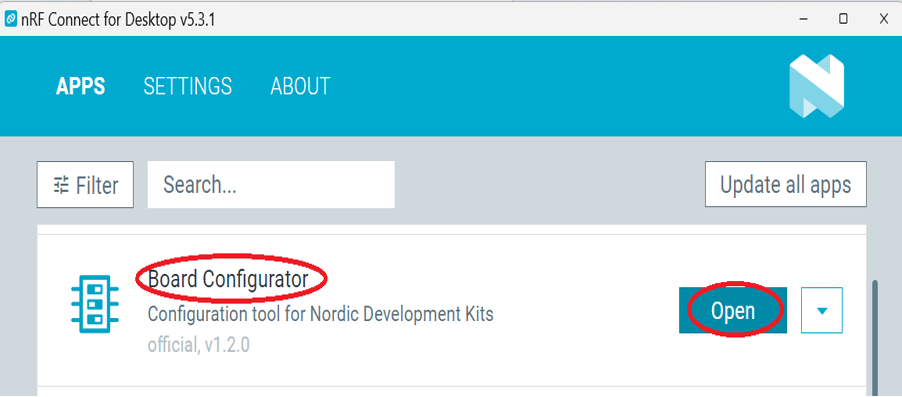
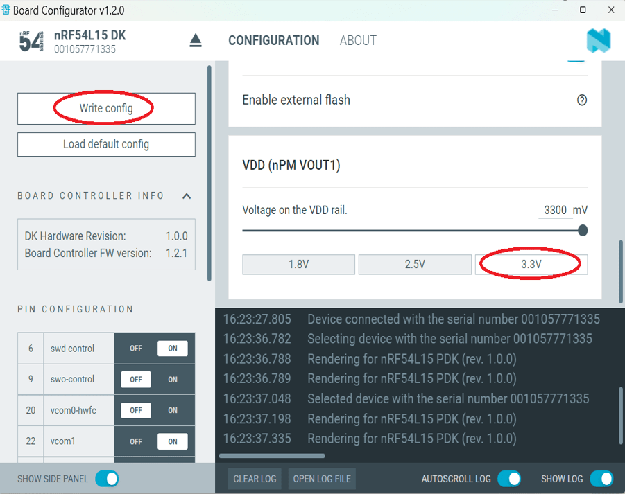
Step 9: CRITICAL BEFORE FLASHING/DEBUGGING: You have to change the VDD voltage configuration on the nRF54L15-DK board to 3.3V. To do this: Launch “nRF Connect for Desktop" -> choose “Board Configurator" -> click “Open"
Change the VDD target selection value to “3.3V" -> click “Write config".
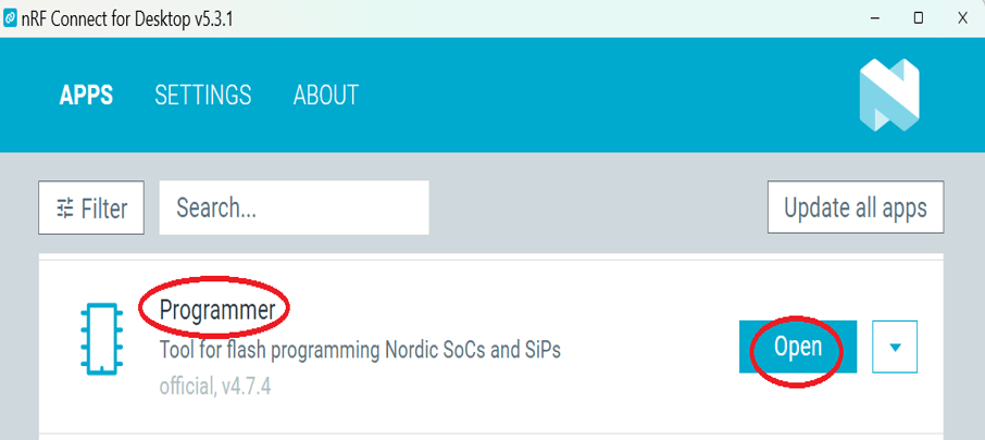
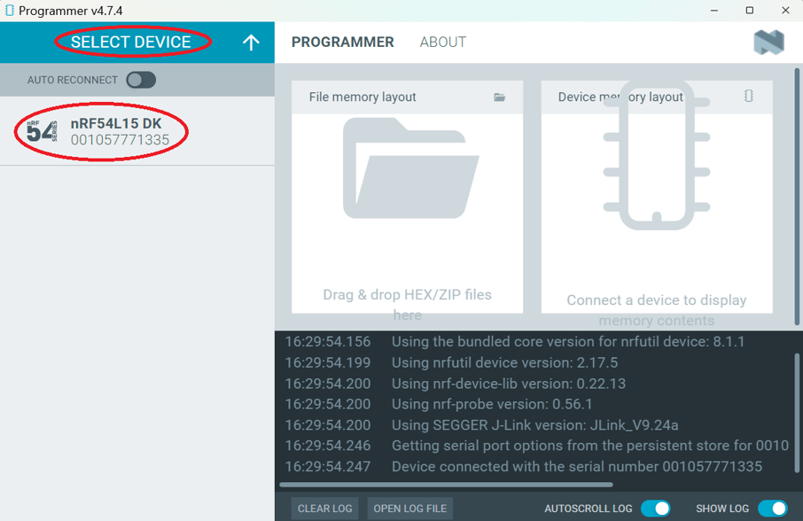
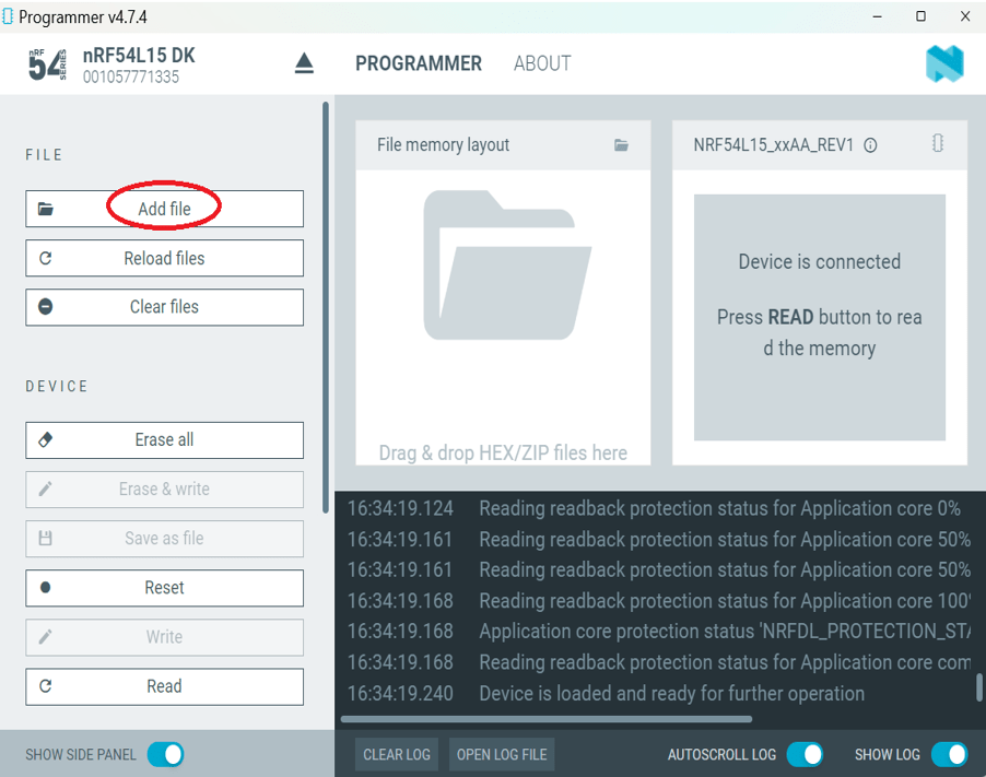
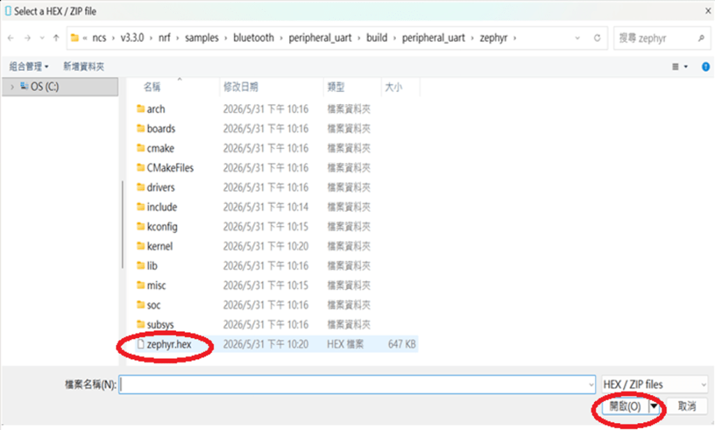
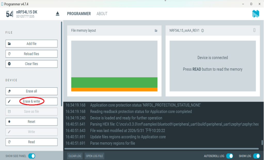
4. Flashing / Programming The nRF Connect SDK (NCS) natively supports direct programming. You can utilize the “Programmer" application tool to flash the compiled zephyr.hex binary file onto the target chip. The exact procedure is detailed below:
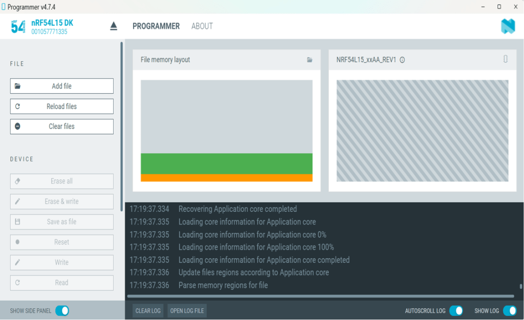
Step 1: Open “nRF Connect for Desktop" -> select “Programmer" and click “Open".
Click “Select Device" and choose “nRF54L15DK".
Click “Add file".
Step 2: Select your compiled target “.hex" file.
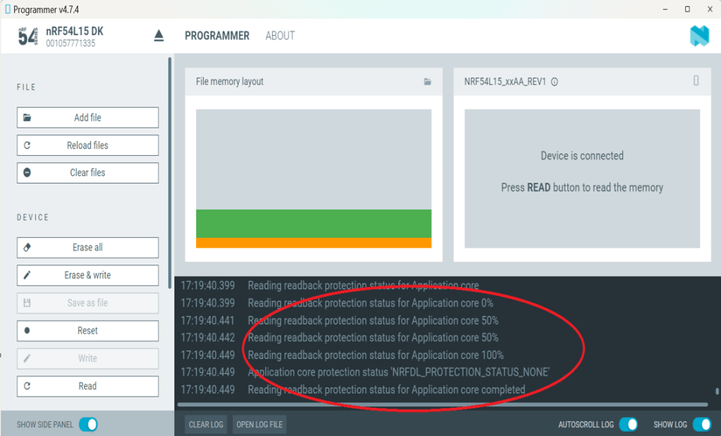
Click “Erase & write" to initiate the programming/flashing process.
While flashing, a progress diagonal pattern will display on the right-hand panel.
When the LOG shows a “completed" status text, it means that the programming/flashing is successfully done.
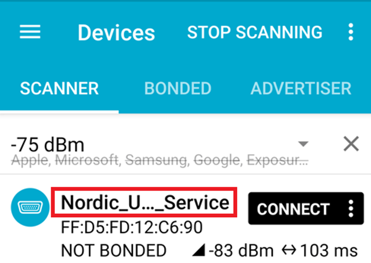
Step 3: After the flash operation completes, you can download the “nRF Connect for Mobile" app to scan and verify that the Raytac AN54LV-DB-15 development board is advertising normally.
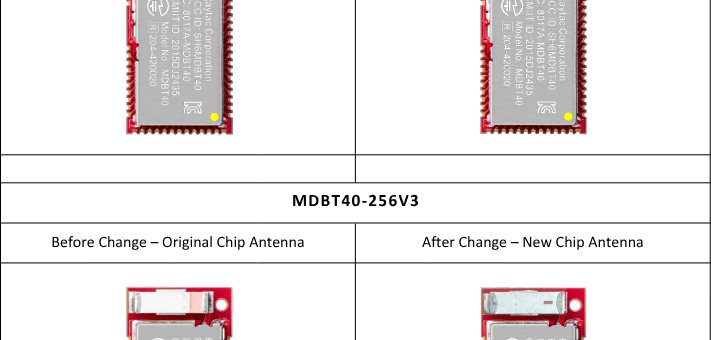
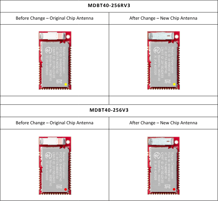
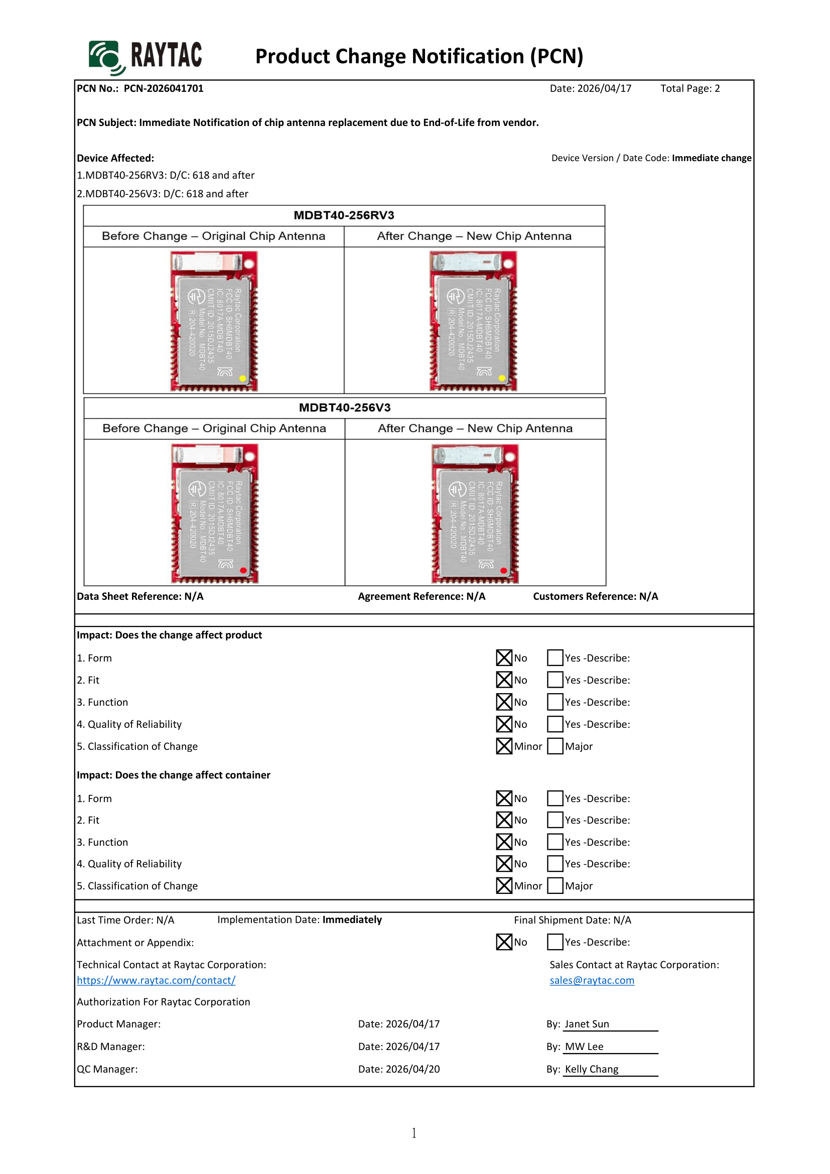
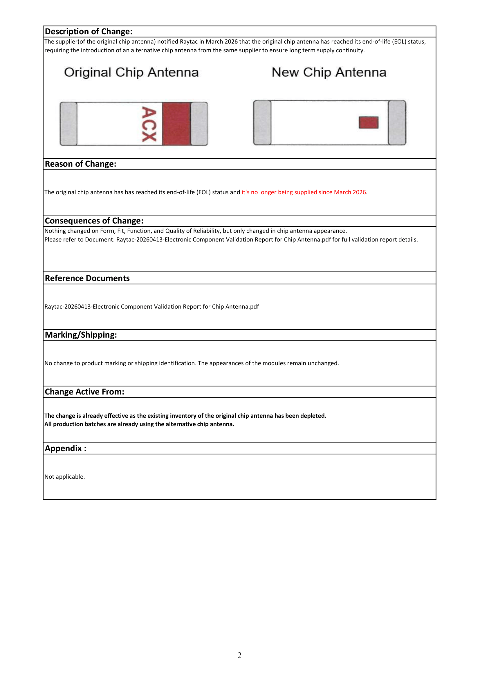
The supplier(of the original chip antenna) notified Raytac in March 2026 that the original chip antenna has reached its end-of-life (EOL) status, thus the introduction of an alternative(new) chip antenna from the same supplier to ensure long term supply continuity.
There are no changes on Form, Fit, Function, and Quality of Reliability. Only change in Chip Antenna Appearance.
Upon receiving this notice, our R&D team promptly conducted comprehensive validation. The results confirm that there is no impact on RF performance, EMC compliance, or related certifications. In conclusion, all existing certifications and technical documentations remain valid.
The change is already effective as the existing inventory of the original chip antenna has been depleted. All production batches are already using the new chip antenna.
We kindly invite our customers, distributors, and partners to update your records accordingly. For any questions or support, and further document requests regarding this update, feel free to reach out to Raytac Sales Team via: sales@raytac.com.
Raytac Corporation 勁達國際電子股份有限公司 / Raytac Corporation (USA) / abietec Inc. A Bluetooth, Wi-Fi, and LoRa Module Maker/ODM & OEM Manufacturer based on Nordic nRF54; nRF53: nRF52; nRF51; nRF7002 Infineon: CYW55912 NXP: RW610, RW612 Semtech: SX1262
Bluetooth Specification: BT6 ; BT5.4 ; BT5.3 ; BT5.2. Wi-Fi Specification: Wi-Fi 6 LoRa Specification: LoRaWAN Zephyr Project Silver Member
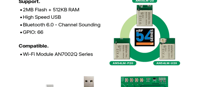
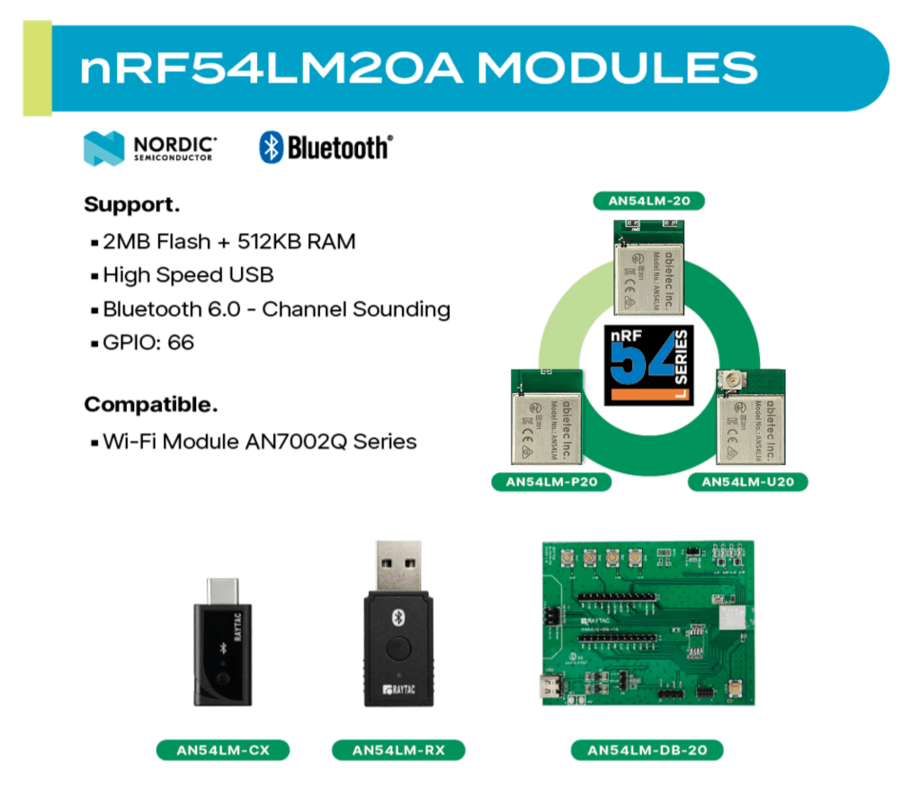
Raytac Group, a worldwide leader in wireless modules, wireless solutions, and a Nordic-recommended third-party module manufacturer, announces the upcoming release of the AN54LM series modules, built on Nordic’s nRF54LM20A/nRF54LM20B SoC.
The series comes in a compact form factor of 9.9 x 13.3 x 2.0 mm (0.39 × 0.52 × 0.08 inches) and offers 3 antenna variants:
The Max output power is +8 dBm and data rates up to 4 Mbps for low-latency applications.
Powered by the nRF54LM20A/B, AN54LM features a high-end dual-core architecture (Arm Cortex-M33 + RISC-V) with up to 2 MB Flash and 512 KB RAM, enabling complex, memory-intensive applications.
In addition to its multi-protocol support, AN54LM series is compatible with the AN7002Q series Wi-Fi modules(nRF7002 solution) to enable Wi-Fi expansions. Know more about the AN7002Q series here.
On the security side, AN54LM series’ hardware and firmware align with EU Cyber Resilience Act (CRA) security principles, helping ensure trusted device operation and lifecycle security.
Alongside modules, Raytac is also working on developing a complete ecosystem, including evaluation boards(Dev Kits) and USB dongles, providing a practical pathway to faster time-to-market for embedded engineers.
“The AN54LM series represents Raytac’s/abietec’s continued commitment to delivering high-quality wireless modules based on Nordic’s solutions." “By combining advanced processing capabilities, multi-protocol support, and a comprehensive development ecosystem, we aim to help all engineers innovate and reduce time-to-market.” — Lyon Liu, CEO, Raytac Group.
[New Taipei City, Taiwan – January 12, 2026] Raytac Corporation, a global leading supplier of Bluetooth, Wi-Fi, and wireless modules, announces a strategic partnership with Acal BFi(Website link) to strengthen wireless connectivity support for customers across Europe. Through this collaboration, Raytac’s portfolio of pre-certified Bluetooth® Low Energy, Wi-Fi, and Wi-Fi + Bluetooth modules will be supported by Acal BFi’s local application engineering and design-in expertise.
Raytac specializes in short-range RF connectivity, delivering production-ready wireless modules optimized for low power consumption, RF robustness, and fast system integration. Additionally, Raytac focuses on simplifying wireless design while ensuring stable performance across demanding industrial, medical, and IoT environments.
Raytac’s module portfolio includes ultra-low-power Bluetooth LE modules, Wi-Fi modules, and versatile Wi-Fi + Bluetooth combo solutions designed for reliable radio coexistence and long-term availability. All Raytac modules are pre-certified to major global regulatory standards, including CE, FCC, IC, UKCA, TELEC, KC, RCM, SRRC, NCC, and WPC, enabling customers to significantly reduce certification time and compliance risk.
“Great ideas deserve great hardware,” said Lyon Liu, CEO, Raytac. “Our mission is to remove complexity from wireless design. Together with Acal BFi, we can now support customers not only with modules, but with the integration expertise to make sure those modules perform in the real world – in metal housings, in noisy RF environments, in medical devices, in smart sensors, wherever reliability matters.”
“Bluetooth and Wi-Fi connectivity is now a core requirement in almost every market we serve – from smart infrastructure and industrial automation to healthcare and sensing,” said Matthias Beuther, Business Development Manager, Acal BFi. “By partnering with Raytac, we are adding a powerful and proven wireless platform to our portfolio. The combination of Raytac’s module technology and our application engineering expertise gives our customers a faster, lower-risk path to market.”
By working closely with Acal BFi’s IoT & Wireless Technology Centre, customers gain access to local technical support covering antenna selection and tuning, power optimization, enclosure considerations, and coexistence validation. This partnership enables a more predictable, minimal-risk path from prototype to volume production for high-reliability wireless products deployed in real-world environments.
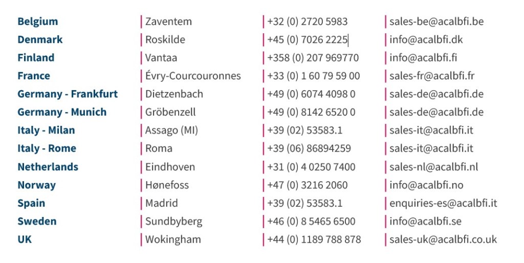
For inquires, please contact the below Acal BFi regional offices:
Edited by Business Development Manager: Tony Yin
Raytac Corporation 勁達國際電子股份有限公司 / Raytac Corporation (USA) / abietec Inc. A Bluetooth, Wi-Fi, and LoRa Module Maker/ODM & OEM Manufacturer based on Nordic nRF54; nRF53: nRF52; nRF51; nRF7002 Semtech Specification: SX1262
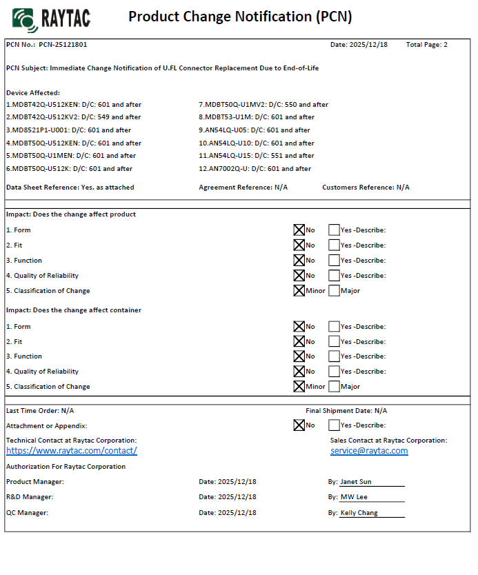
There are no changes on Form, Fit, Function, and Quality of Reliability. Only change in u.FL Connector Appearance. All existing certifications and technical documentations remain valid.
We kindly invite our customers, distributors, and partners to update your records accordingly. For any questions or support regarding this update, feel free to reach out via: sales@raytac.com.
Raytac Corporation 勁達國際電子股份有限公司 / Raytac Corporation (USA) / abietec Inc. A Bluetooth, Wi-Fi, and LoRa Module Maker/ODM & OEM Manufacturer based on Nordic nRF54; nRF53: nRF52; nRF51; nRF7002 Semtech Specification: SX1262
New U.S. Headquarter Address: 17800 Castleton Street, Suite 238, City of Industry, CA 91748, USA Phone: 626.328.3827 Our new location strengthens our operational capabilities in the United States, enabling faster logistics, enhanced customer support, and expanded service coverage. We look forward to continuing to serve our partners and customers from our new facility.
Raytac Corporation 勁達國際電子股份有限公司 / Raytac Corporation (USA) / abietec Inc. A Bluetooth, Wi-Fi, and LoRa Module Maker/ODM & OEM Manufacturer based on Nordic nRF54; nRF53: nRF52; nRF51; nRF7002 Semtech Specification: SX1262
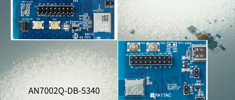
Raytac has advanced the dev kit version of bundle offer – WIFI+BLE: AN7002Q-DB- 5340-M with an on-board flash memory(MX25R64) to create easy evaluation for Wi-Fi project developments.
[January 2026 Update] In this article, we will talk about: Project WITH External Flash MX25R64(8MB) applied – Connecting through SPI between nRF5340 module: MDBT53-1M(BLE) & nRF7002 module: AN7002Q(WIFI) – Connecting through QSPI (XIP) between MDBT53-1M and external memory MX25R64
Table of Content———————————————————————————————————
Hardware Set Up A. Project WITHOUT External Flash MX25R64 needed B. Project WITH External Flash MX25R64 needed
Software Resources & Preparations
Firmware Build & Compile A. Project WITHOUT External Flash MX25R64 needed B. Project WITH External Flash MX25R64 needed
Note: Pease make sure to have both “Nordic nRF5340-DK” and “AN7002Q-DB-5340-M”connected and running during the WIFI+BLE (nRF7002+nRF5340) project development.
Hardware Network: IDC Ribbon Wire(J-Link Cable): Connect nRF5340-DK to AN7002Q-DB-5340-M USB Wire –Type C USB: Power supply to AN7002Q-DB-5340-M through USB TYPE-C USB Wire-Micro USB: Power supply to nRF5340-DK through Micro USB
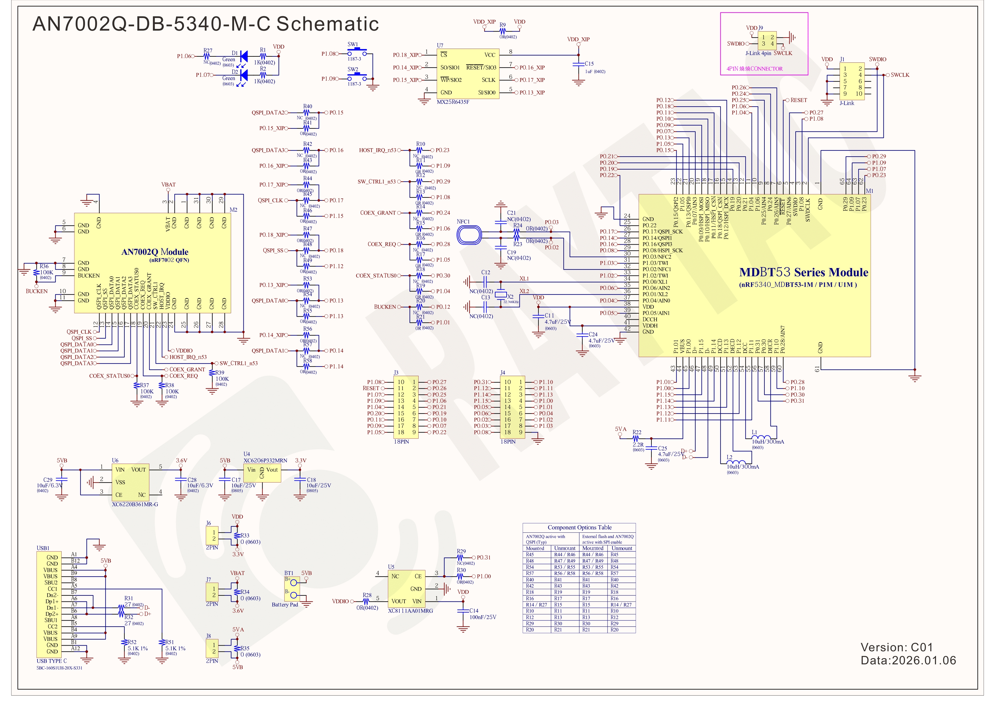
Schematic diagram of AN7002Q-DB-5340-M can be referenced for design as follows. *nRF7002 module <- SPI -> nRF5340 module *MX256R NOR Flahs <-QSPI-> nRF7002 module (Click on the image to zoom in.)
!! Important Note:!! The circuit of SW1(p1.08)/SW2(p1.09)/LED1(p1.06) on AN7002Q-DB-5340-M is NOT COMPATIBLE to Nordic WI-FI Control Pin of swctrl1(p1.08)/host_irq(p1.09)/grant(p1.06). In this case, if you’re working with external flash MX25R64 for the WIFI project, Please avoid pin SW1/SW2/LED1 usage while LED2(p1.07) remains available as normal usage. For the PCB design of end product/end device(mounted with AN7002Q & MDBT53 modules), the switch & LED should be configured to be: SW1(p0.23)/SW2(p0.24)/LED1(p0.28).
Step 1: Prepared with the latest version of nRF Connect for Desktop, using Windows 64-bit – 5.2.0 Step 2: Prepared with the latest version of Command Line Tools, using Windows X86 64 – 10.24.2
**Note: SEGGER J-LINK Upgrade message might pop up while you’re doing above downloads.
Step 3: Locate all the necessary kits for programming in PC
3. Firmware Build & Compile After you download and set up nRFConnect SDK (NCS), you will be able to apply free VS (Visual Studio) Code IDE as firmware programming tool.
The below example uses NCS v3.1.1 and runs the program under: C:\ncs
Step 1: Start with a Wi-Fi Scan project and run the program under: C:\ncs\v3.1.1\raytac <<Create a new application and Copy a sample>>
Step 2: Select SDK v3.1.1 to copy the sample
Step 3: Select example by entering keyword: wifi scan(Wi-Fi Scan)
Step 4: Enter application location: C:\ncs\v3.1.1\raytac and name the project as: wifi_scan_uart_dfu
Step 5: Open an existing application and find the registered project: wifi_scan_uart_dfu
Step 6: How to activate the Devicetree setting of Wi-Fi nRF7002 and Create file:nrf5340dk_nrf5340_cpuapp.overlay Code example is as follows: / { chosen { aliases { /delete-node/ leds; /delete-node/ buttons; }; };
Step 7: It is required to do MCUBoot before working with DFU using External Flash Please do the code configuration in sysbuild.conf as following reference code.
SB_CONFIG_BOOTLOADER_MCUBOOT=y # DFU with UART SB_CONFIG_MCUBOOT_MODE_SINGLE_APP=n
# DFU with external flash SB_CONFIG_PM_EXTERNAL_FLASH_MCUBOOT_SECONDARY=y
Step 8: It is required to doMCUMGR before working with DFU over UART Please do the code configuration in prj.conf as following reference code.
# Enable QSPI driver for Application CONFIG_NORDIC_QSPI_NOR=y
# Enable mcumgr DFU in application CONFIG_MCUMGR=y CONFIG_NET_BUF=y CONFIG_ZCBOR=y CONFIG_CRC=y
# Enable mcumgr management for both OS and Images CONFIG_MCUMGR_GRP_OS=y CONFIG_MCUMGR_GRP_IMG=y CONFIG_FLASH=y CONFIG_IMG_MANAGER=y CONFIG_STREAM_FLASH=y CONFIG_FLASH_MAP=y
# Configure MCUMGR transport to UART CONFIG_MCUMGR_TRANSPORT_UART=y CONFIG_BASE64=y
Step 9: Add with MCUBoot setting , and create a root for sysbuild ; Build with file mucboot.overlay & file mcuboot.conf
9A. To the File: mucboot.overlay &mx25r64 { status = “okay"; };
Step 10: Create a VERSION file by referencing the following code when testing DFU over UART. VERSION_MAJOR = 99 VERSION_MINOR = 0 PATCHLEVEL = 0 VERSION_TWEAK = 0 EXTRAVERSION =
Step 14: Generate a Merged.hex file after compiling the program
Step15: You can choose Build/Debug/Flash under ACTIONS during development << Build >>
<< Debug >>
<< Flash >>
Step 16: Go to ACTIONS >> Memory report to check the memory partitions.
Now you can see partitions available in the system. mcu_secondary has already been located in MX25R64 flash memory.
4. Test/Validate DFU Process & WIFI SCAN After the firmware programmed to MDBT53 module on board, we use the USB to UART adaptor board for connecting AN7002Q-DB-5340-M through: A. MCUMGR UART to PC and through: B. WiFi Scan UART to PC respectively. Note: We suggest you finish connecting A. and B. before running tests.
Now we can run the tests.
A. DFU over UART – Using AuTerm Program 1. We can locate Image version=V99.0.0 under the current VERSION file
It also indicates Image version: 99.0.0 in MCUmgr-Slot 0.
2. Try to modify the file version from V99 to V100 under VERSION file: VERSION_MAJOR = 100
VERSION_MINOR = 0
PATCHLEVEL = 0
VERSION_TWEAK = 0
EXTRAVERSION =
And go with “Pristine Build”
3. We’re about to run DFU over UART , Please DO NOT do “Flash” or “Erase”.
Proceed with “Force reboot”
4. It’s now Version 100.0.0 in Slot 0 under MCUgr ⭢ DFU over UART successfully done!
Before it was Version 99.0.0 in Slot 1 under MCUgr.
B. WIFI SCAN – PuTTY Console WIFI SCAN credentials can be located under PC Console – PuTTY.
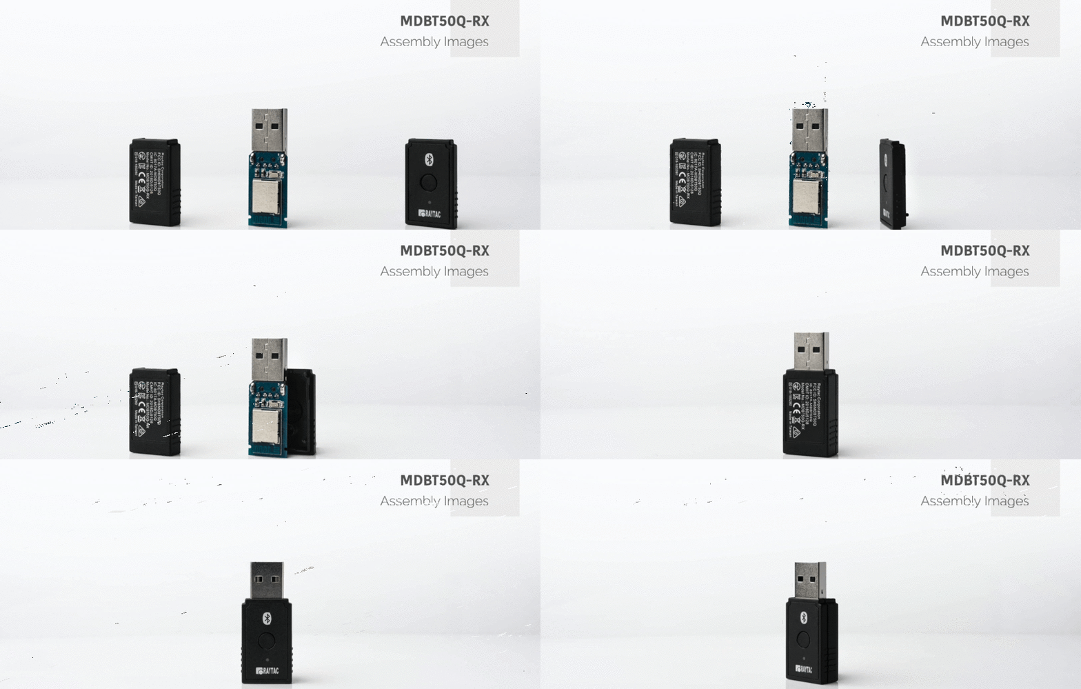
Raytac Corporation would like to inform all customers and partners of an official Product Change Notice: PCN-25100801 regarding the following product series:
Affected Series MDBT50Q-RX Series (nRF52840/833 based USB-A dongles)
Update of Raytac’s company logo on the nameplate, and
Addition of NCC logo on the back label.
There are no changes to product function, performance, quality, form factor, or safety compliances. All existing certifications and technical documentations remain valid.
We kindly invite our customers, distributors, and partners to update your records accordingly. For any questions or support regarding this update, feel free to reach out via: service@raytac.com.
Full details of the PCN please see below(Click on the images to zoom in). Remark: Please take note of the final shipment date.
Edited by Business Development Manager: Tony Yin
Raytac Corporation 勁達國際電子股份有限公司 / Raytac Corporation (USA) / abietec Inc. A Bluetooth, Wi-Fi, and LoRa Module Maker/ODM & OEM Manufacturer based on Nordic nRF54; nRF53: nRF52; nRF51; nRF7002 Semtech Specification: SX1262
[New Taipei, Taiwan / Los Angeles, USA] We’re thrilled to announce that Raytac Group, including Raytac Corporation(USA) and abietec Inc., will be joining Embedded World North America 2025, in November 4-6 at the Anaheim Convention Center, CA. Come find us at Booth #5067!
This year, we’re bringing lots of exciting news: From Raytac:
Brand-new Nordic nRF54L series modules: AN54LQ and AN54LV(Product Link), built for Bluetooth® LE 6.0 with ultra-low power and strong RF performance.
A full Channel Sounding demo on how precise measurement of multipath and distance can enhance real-time location accuracy, improve signal reliability, and optimize antenna placement.
Introducing you to our Ecosystem, including all our partners and technologies used in various applications.
Discover how our modules can reduce development time and costs, making your projects more efficient.
One-on-one consultations with our experts to help you find the right solutions for your needs.
From abietec:
ODM/OEM design services for everything wireless: Bluetooth®, Wi-Fi, mmWave, LoRa, NB-IoT… You name it!
More importantly, Stop by our booth to explore new products, join fun interactive games, and win prizes!
Let Raytac & abietec be your bridge to product success, connecting great ideas with real-world wireless solutions.
We’re waiting for you at: Hall C – Level 1 Booth 5067













 Raytac Corporation