There are no changes on Form, Fit, Function, and Quality of Reliability. Only change in u.FL Connector Appearance. All existing certifications and technical documentations remain valid.
We kindly invite our customers, distributors, and partners to update your records accordingly. For any questions or support regarding this update, feel free to reach out via: sales@raytac.com.
Raytac Corporation 勁達國際電子股份有限公司 / Raytac Corporation (USA) / abietec Inc. A Bluetooth, Wi-Fi, and LoRa Module Maker/ODM & OEM Manufacturer based on Nordic nRF54; nRF53: nRF52; nRF51; nRF7002 Semtech Specification: SX1262
Raytac’s AN54LQ & AN54LV modules, powered by Nordic Semiconductor’s nRF54L family SoCs, come in multiple form factors and antenna options, ensuring your seamless integration into compact, RF-sensitive, or performance-driven designs.
Whether you need a: ☑ Chip antenna; ☑ PCB antenna; ☑ u.FL connector; ☑ Antenna Pin,
Or you want Small, Smaller, or Smallest, we always have a solution that fits best! *All products are pre-certified with FCC, IC, CE, UKCA, Telec, KC, SRRC, NCC, RCM, WPC.
New U.S. Headquarter Address: 17800 Castleton Street, Suite 238, City of Industry, CA 91748, USA Phone: 626.328.3827 Our new location strengthens our operational capabilities in the United States, enabling faster logistics, enhanced customer support, and expanded service coverage. We look forward to continuing to serve our partners and customers from our new facility.
Raytac Corporation 勁達國際電子股份有限公司 / Raytac Corporation (USA) / abietec Inc. A Bluetooth, Wi-Fi, and LoRa Module Maker/ODM & OEM Manufacturer based on Nordic nRF54; nRF53: nRF52; nRF51; nRF7002 Semtech Specification: SX1262
Raytac has advanced the dev kit version of bundle offer – WIFI+BLE: AN7002Q-DB- 5340-M with an on-board flash memory(MX25R64) to create easy evaluation for Wi-Fi project developments.
Table of Content———————————————————————————————————
Hardware Set Up A. Project WITHOUT External Flash MX25R64 needed B. Project WITH External Flash MX25R64 needed
Software Resources & Preparations
Firmware Build & Compile A. Project WITHOUT External Flash MX25R64 needed B. Project WITH External Flash MX25R64 needed
Note: Pease make sure to have both “Nordic nRF5340-DK” and “AN7002Q-DB-5340-M”connected and running during the WIFI+BLE (nRF7002+nRF5340) project development.
Hardware Network: IDC Ribbon Wire(J-Link Cable): Connect nRF5340-DK to AN7002Q-DB-5340-M USB Wire –Type C USB: Power supply to AN7002Q-DB-5340-M through USB TYPE-C USB Wire-Micro USB: Power supply to nRF5340-DK through Micro USB
A. Project WITHOUT External Flash MX25R64 needed – Allocate QSPI for communication between MDBT53 (BLE) and AN7002Q (WIFI) – External flash MX25R64 flash memory is not activated – NO additional resistor swapping needed, keep it as it is on board now. The Resistors on board align with the Nordic board definition (same as nRF7002-DK). – Please closely follow the definition chart printed on back side of board AN7002Q-DB-5340-M. “Component Options Table” > “AN7002Q active with QSPI (Typ)”
– Photo showing the resistor allocation:
– Schematic of the AN7002Q-DB-5340-M(Click on the image to zoom in):
B. Project WITH External Flash MX25R64 needed – Allocate SPI for communication between MDBT53 (BLE) and AN7002Q (WIFI) – Allocate QSPI for XIP: External flash MX25R64 is activated – It is REQUIRED to reallocate resistors to swap the QSPI and SPI on the AN7002Q-DB-5340-M in order to activate the circuit for MX25R64. – Do necessary resistors swapping manually (closely follow the definition chart printed on back side of board AN7002Q-DB-5340-M.) “Component Options Table” > “External flash and AN7002Q active with SPI enable”
– Photo showing the resistor allocation: Detach the resistor -R27 “Component Options Table” > “External flash and AN7002Q active with SPI enable” <<< Necessary resistors swapping manually needed ↓ >>>
– Schematic of the AN7002Q-DB-5340-M(Click on the image to zoom in): Modify the above resistors swapped and necessary component based on the chart: “Component Options Table” > “External flash and AN7002Q active with SPI enable”
!! Important Note:!! The circuit of SW1(p1.08)/SW2(p1.09)/LED1(p1.06) on AN7002Q-DB-5340-M is NOT COMPATIBLE to Nordic WI-FI Control Pin of swctrl1(p1.08)/host_irq(p1.09)/grant(p1.06). In this case, if you’re working with external flash MX25R64 for the WIFI project, Please avoid pin SW1/SW2/LED1 usage while LED2(p1.07) remains available as normal usage. For the design perspective of mother board/carrier board /target board (mounted with AN7002Q & MDBT53 modules), it is required to design the circuit align to SW1(p0.23)/SW2(p0.24)/LED1(p0.28).
Step 1: Prepared with the latest version of nRF Connect for Desktop, using Windows 64-bit – 5.2.0 Step 2: Prepared with the latest version of Command Line Tools, using Windows X86 64 – 10.24.2
**Note: SEGGER J-LINK Upgrade message might pop up while you’re doing above downloads.
Step 3: Locate all the necessary kits for programming in PC
3. Firmware Build & Compile After you download and set up nRFConnect SDK (NCS), you will be able to apply free VS (Visual Studio) Code IDE as firmware programming tool. Here’re the guidelines to developing programs without/with External Flash MX25R64.
A. Project WITHOUT External Flash MX25R64 needed You can directly build/compile on Nordic NCS without any additional configurations/modifications needed.
B. Project WITH External Flash MX25R64 needed – Allocate SPI for communication between MDBT53 (BLE) and AN7002Q (WIFI) – Allocate QSPI for XIP: External flash MX25R64 is activated
The below example uses NCS v3.1.1 and runs the under: C:\ncs
Step 1: Start with a Wi-Fi Scan project and run the program under: C:\ncs\v3.1.1\raytac <<Create a new application and Copy a sample>>
Step 2: Select SDK v3.1.1 to copy the sample
Step 3: Select example by entering keyword: wifi scan(Wi-Fi Scan)
Step 4: Enter application location and name the project as: wifi_scan_uart_dfu
Step 5: Open an existing application and find the registered project: wifi_scan_uart_dfu
★★How to activate the Devicetree setting of Wi-Fi nRF7002 and Create file:nrf5340dk_nrf5340_cpuapp.overlay Code example is as follows: / { chosen { aliases { /delete-node/ leds; /delete-node/ buttons; }; };
Step 7: It is required to do MCUBoot before working with DFU using External Flash Please do the code configuration in sysbuild.conf as following reference code.
SB_CONFIG_BOOTLOADER_MCUBOOT=y # DFU with UART SB_CONFIG_MCUBOOT_MODE_SINGLE_APP=n
# DFU with external flash SB_CONFIG_PM_EXTERNAL_FLASH_MCUBOOT_SECONDARY=y
Step 8: It is required to do MCUMGR before working with DFU over UART Please do the code configuration in prj.conf as following reference code.
# Enable QSPI driver for Application CONFIG_NORDIC_QSPI_NOR=y
# Enable mcumgr DFU in application CONFIG_MCUMGR=y CONFIG_NET_BUF=y CONFIG_ZCBOR=y CONFIG_CRC=y
# Enable mcumgr management for both OS and Images CONFIG_MCUMGR_GRP_OS=y CONFIG_MCUMGR_GRP_IMG=y CONFIG_FLASH=y CONFIG_IMG_MANAGER=y CONFIG_STREAM_FLASH=y CONFIG_FLASH_MAP=y
# Configure MCUMGR transport to UART CONFIG_MCUMGR_TRANSPORT_UART=y CONFIG_BASE64=y
Step 9: Add with MCUBoot setting , and create a root for sysbuild ; Build with file mucboot.overlay & file mcuboot.conf
9A. With mucboot.overlay &mx25r64 { status = “okay"; };
Step 10: Create a VERSION file by referencing the following code when testing DFU over UART. VERSION_MAJOR = 99 VERSION_MINOR = 0 PATCHLEVEL = 0 VERSION_TWEAK = 0 EXTRAVERSION =
Step 14: Generate a Merged.hex file after compiling the program
Step15: You can choose Build/Debug/Flash under ACTIONS during development << Build >>
<< Debug >>
<< Flash >>
Step 16: Go to ACTIONS >> Memory report
Now you can see partitions available in the system. mcu_secondary has already been located in MX25R64 flash memory.
4. Test/Validate DFU Process & WIFI SCAN After the firmware programmed to MDBT53 module on board, we use the USB to UART adaptor board for connection AN7002Q-DB-5340-M through: A. MCUMGR UART to PC and through: B. WiFi Scan UART to PC respectively. Note: We suggest you finish connecting A. and B. before running tests.
Now we can run the tests.
A. DFU over UART – Using AuTerm Program 1. We can locate Image version=V99.0.0 under the current VERSION file
It also indicates Image version: 99.0.0 in MCUmgr-Slot 0.
2. Try to modify the file version from V99 to V100 under VERSION file: VERSION_MAJOR = 100
VERSION_MINOR = 0
PATCHLEVEL = 0
VERSION_TWEAK = 0
EXTRAVERSION =
And go with “Pristine Build”
3. We’re about to run DFU over UART , Please DO NOT do “Flash” or “Erase”.
Proceed with “Force reboot”
4. It’s now Version 100.0.0 in Slot 0 under MCUgr ⭢ DFU over UART successfully done!
Before it was Version 99.0.0 in Slot 1 under MCUgr.
B. WIFI SCAN – PuTTY Console WIFI SCAN credentials can be located under PC Console – PuTTY.
Bluetooth Channel Sounding adds a new dimension to wireless connectivity by combining secure data transfer with the low‑power, low‑cost Bluetooth technology already trusted worldwide — now extended to deliver precise location awareness. This evolution means IoT devices can gain both communication and ranging capabilities in a single, efficient platform. With tens of centimeter distance accuracy, Channel Sounding enables practical new use cases such as secure access, proximity‑based services, indoor navigation, and ‘Find My’ functionality.
Android 16 now supports Channel Sounding APIs, making it possible for developers to access this capability directly on flagship devices like the Pixel 10. With anticipated pervasive adoption across the mobile ecosystem, Channel Sounding is positioned to scale broadly and become a standard feature for IoT applications.
The onceLabs demo was reported as the first of its kind in August, gaining notability on LinkedIn(Post link) — and is now being shown for the first time in a public venue. onceLabs’ free BLE Hero app(Download Link) is a sniffer, analyzer, and development tool, available in app stores, and can be seen in action during the live demo. The Android version has been updated to capture and display Channel Sounding data, giving developers clear insight into ranging accuracy and system performance. Since 2018, Raytac and onceLabs have collaborated to bring new Bluetooth capabilities from specification to market‑ready solutions. Raytac’s proven hardware platforms and onceLabs’ application‑layer software expertise combine to accelerate adoption of emerging standards, showing how partnership can translate advanced technology into product‑ready functionality.
QR code on the left: watch the Channel Sounding Live Demo; QR code on the right: download the BLE Hero app on Google Play.
“Our collaboration with onceLabs has always been about enabling customers to move quickly and confidently with the latest Bluetooth technology,” said Lyon Liu, CEO of Raytac Corporation. “This live demo of Channel Sounding is another example of how our partnership delivers not just modules, but complete solutions that inspire new applications.”
Together, Raytac and onceLabs are demonstrating how Bluetooth Channel Sounding can move from specification to practical demonstrations that product companies can act on.
“With Raytac providing the hardware foundation and onceLabs delivering the application software, we continue to support customers in translating new Bluetooth features into real use cases,” said Joseph Bakalor, President and CTO of onceLabs. “Channel Sounding is a perfect example — and with our expertise in Zephyr RTOS, developers can build on open, production‑ready software that scales from prototype to deployment.”
The Raytac + onceLabs demo will be featured in Raytac Booth 5067 at embedded world North America, November 4–6, 2025, at the Anaheim Convention Center. Attendees are invited to visit the booth to see the demo in action and learn how Raytac and onceLabs can support their next wireless product.
About Raytac Raytac Corporation is a leading provider of wireless modules, offering one of the industry’s broadest portfolios of pre‑certified solutions built on Nordic Semiconductor SoCs. With a focus on quality, reliability, and ease of integration, Raytac helps product companies accelerate development and reduce risk when bringing wireless products to market. From consumer devices to industrial applications, Raytac modules are trusted worldwide for their performance, compliance, and long‑term availability. Company website: www.raytac.com
About onceLabs onceLabs delivers custom embedded firmware and mobile application software with a passion for translating client use cases into cloud‑enabled applications that leverage the latest wireless innovations. Known for delivering quality user experiences while optimizing performance and power consumption, onceLabs helps bring products to life through custom software. With design expertise spanning Bluetooth LE, Wi‑Fi, cellular, and other wireless protocols — and a strong engineering foundation in both embedded and mobile software — onceLabs accelerates time‑to‑market through a systems approach to architecture, continuous integration, and real‑world reliability. Company website: www.oncelabs.com
Edited by Business Development Manager: Tony Yin
Raytac Corporation 勁達國際電子股份有限公司 / Raytac Corporation (USA) / abietec Inc. A Bluetooth, Wi-Fi, and LoRa Module Maker/ODM & OEM Manufacturer based on Nordic nRF54; nRF53: nRF52; nRF51; nRF7002 Semtech Specification: SX1262
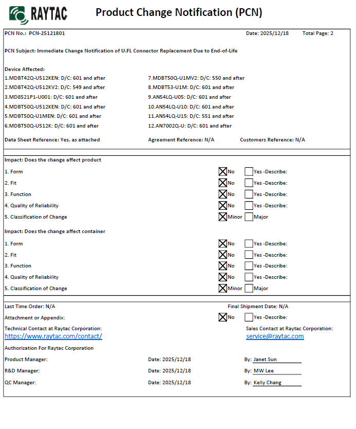
Raytac Corporation would like to inform all customers and partners of an official Product Change Notice: PCN-25100801 regarding the following product series:
Affected Series MDBT50Q-RX Series (nRF52840/833 based USB-A dongles)
Update of Raytac’s company logo on the nameplate, and
Addition of NCC logo on the back label.
There are no changes to product function, performance, quality, form factor, or safety compliances. All existing certifications and technical documentations remain valid.
We kindly invite our customers, distributors, and partners to update your records accordingly. For any questions or support regarding this update, feel free to reach out via: service@raytac.com.
Full details of the PCN please see below(Click on the images to zoom in). Remark: Please take note of the final shipment date.
Edited by Business Development Manager: Tony Yin
Raytac Corporation 勁達國際電子股份有限公司 / Raytac Corporation (USA) / abietec Inc. A Bluetooth, Wi-Fi, and LoRa Module Maker/ODM & OEM Manufacturer based on Nordic nRF54; nRF53: nRF52; nRF51; nRF7002 Semtech Specification: SX1262
[New Taipei, Taiwan / Los Angeles, USA] We’re thrilled to announce that Raytac Group, including Raytac Corporation(USA) and abietec Inc., will be joining Embedded World North America 2025, in November 4-6 at the Anaheim Convention Center, CA. Come find us at Booth #5067!
This year, we’re bringing lots of exciting news: From Raytac:
Brand-new Nordic nRF54L series modules: AN54LQ and AN54LV(Product Link), built for Bluetooth® LE 6.0 with ultra-low power and strong RF performance.
A full Channel Sounding demo on how precise measurement of multipath and distance can enhance real-time location accuracy, improve signal reliability, and optimize antenna placement.
Introducing you to our Ecosystem, including all our partners and technologies used in various applications.
Discover how our modules can reduce development time and costs, making your projects more efficient.
One-on-one consultations with our experts to help you find the right solutions for your needs.
From abietec:
ODM/OEM design services for everything wireless: Bluetooth®, Wi-Fi, mmWave, LoRa, NB-IoT… You name it!
More importantly, Stop by our booth to explore new products, join fun interactive games, and win prizes!
Let Raytac & abietec be your bridge to product success, connecting great ideas with real-world wireless solutions.
We’re waiting for you at: Hall C – Level 1 Booth 5067
In this article, Stanley Huang, MSc, Deputy Manager of Firmware Development at Raytac, shares insights on how Raytac’s modules and development kits strengthen the Zephyr ecosystem.
[Stanley Huang, New Taipei City] When we talk about open-source platforms like Zephyr RTOS, most people immediately think of major chip manufacturers such as ST Micro, NXP, or Nordic. But to me, what truly makes Zephyr famous amongst the developer community is through modules that developers can actually touch: those they can instantly plug in and start using right away. In these terms, Raytac is one of the most underrated and important contributors in this ecosystem.
Raytac Modules Make Zephyr More Accessible Instead of being a chip vendor, we specialize in producing high-quality, globally certified modules – especially Bluetooth and Wi-Fi modules based on Nordic chipsets, such as the AN7002Q, AN54LQ, AN54LV, MDBT53, MDBT50Q, and MDBT42Q. All these modules are already certified with Regional RF compliances(FCC, IC, CE, KC, etc.) and the latest Bluetooth Specifications, offering developers the assurance of “plug and play” and “production-ready” solutions. We assure that our modules have become one of the easiest platforms for Zephyr developers to test BLE functionality.
I paired Zephyr with Raytac’s MDBT50Q-DB-40 development board when I first applied Zephyr in a BLE Peripheral project . With a simple west build -b nrf52840dk_nrf52840 followed by flashing the firmware using J-Link or nRF Connect for Desktop, the BLE beacon immediately showed up on my phone. Clean, simple, noise-free, and developer-friendly – that’s Raytac’s style.
Modules play an invaluable role in product development Many would say Raytac only makes modules and the real core is still Nordic’s SoC. But I believe that in an open-source system like Zephyr, the hardware that helps your project runs first is that which contributes the most. Our Zephyr-registered development kits eliminate the hassles of manual soldering, regulatory certification, and antenna design, allowing engineers to fully focus on developing applications based on Zephyr. They can run Zephyr’s BLE peripheral, central, GATT, and HCI samples directly on the Raytac kits that act as a one-stop hardware solution. In many ways, Raytac has pushed Zephyr’s usability a significant step forward.
Raytac Also Expands Zephyr’s Application Horizon Many of Raytac’s modules are ultra-compact- ideal for wearables, smart sensors, and low-power beacons…etc. These are the scenarios where Zephyr excels, and Raytac’s modules provide the physical platform to enable companies to build their “dream devices". When running Zephyr on a tiny module like the AN54LV-15(Product Link), developers will be amazed that something smaller than a piece of corn kernel can run a full RTOS, manage the BLE stack, trigger timers, drive I2C sensors, and even connect to the cloud, all by itself. This combination doesn’t just make development easier – it inspires developers to realize that: “they can build their projects using Raytac’s hardware.”
Raytac may not be the star, but we’re always ready for you On Zephyr’s main stage, companies like Nordic, STM, and Intel take the spotlight, but Raytac plays an essential supporting role – supporting the performance from behind the scenes. We offer stable, high quality, and low-power platforms, giving every line of Zephyr code a place to run and every feature a cornerstone. Our greatest value lies in helping developers skip antenna design and RF interference concerns – so they can jump right into the Zephyr ecosystem with ease.
Our products deliver the reliability you need and the efficiency you expect.
[08/14/2025, California, USA] To better support our customers in the United States, Raytac Corporation(USA) now offers inland domestic shipping and a local support team based in California.
By bringing our services closer to U.S. clients, we can provide faster assistance for ongoing projects, significantly shorten lead times, and maintain the high quality and global compliance standards Raytac is known for.
Hi readers, did you know that Raytac offers a special service exclusively for our customers? 😉 We offer support services: HEX file verification and flashing firmware into modules per customer’s requests. Compared to the series nRF52 and nRF53’s 2 in 1 or 3 in 1 merged hex files, nRF54L15 requires something slightly different. Following are the tips and suggestions.
Find System Build (sysbuild) ➝ Choose Build System Default
Click Generate and Build
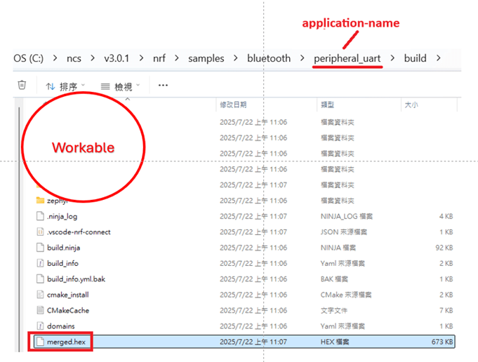
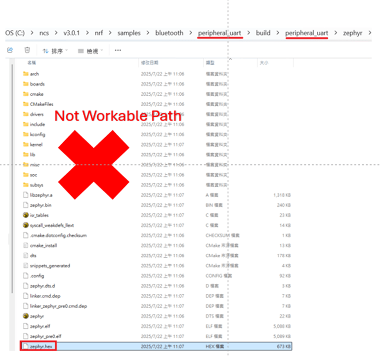
Starting from NCS v2.8.0 (including later versions), the .hex file can be generated in two different paths. 1. ..\nrf\samples\bluetooth\application-name\build\merged.hex 2. ..\nrf\samples\bluetooth\application-name\build\application-name\zephyr\zephyr.hex
Using the AN54LQ/AN54LV series as an example: When you provide the programming file (.hex) for production, please ensure that the file is taken from the following path: 1. ..\nrf\samples\bluetooth\application-name\build\merged.hex And we also do not recommend renaming the merged HEX file due to Nordic suggestions.
Not recommended path: 2. ..\nrf\samples\bluetooth\application-name\build\application-name\zephyr\zephyr.hex The zephyr.hex file is not recommended to be used for flashing or verification in the production process.
Thank you all for your patience in reading! Best wishes for your projects – your success is Raytac’s success! 😊