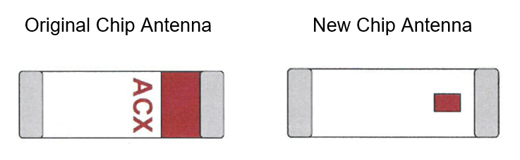
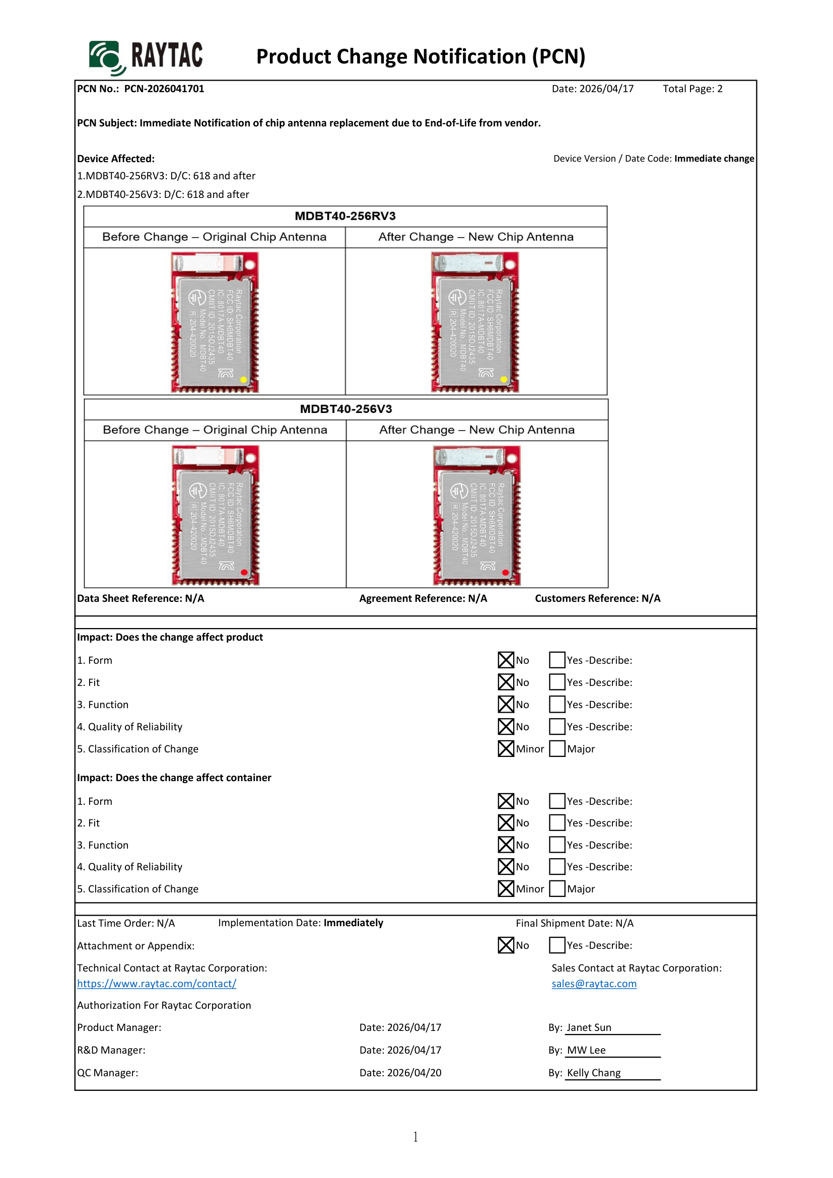
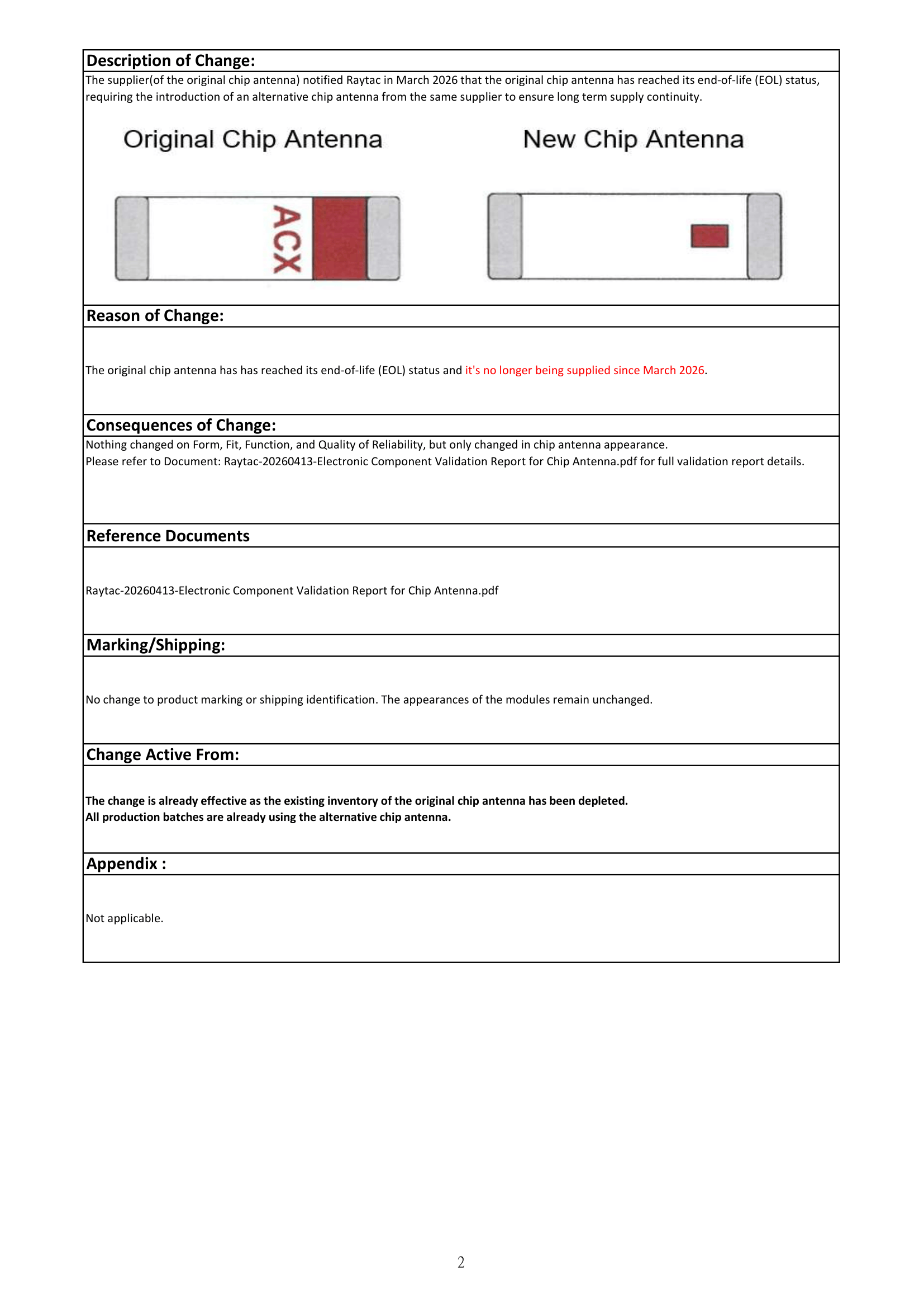
The supplier(of the original chip antenna) notified Raytac in March 2026 that the original chip antenna has reached its end-of-life (EOL) status, thus the introduction of an alternative(new) chip antenna from the same supplier to ensure long term supply continuity.
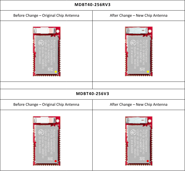
There are no changes on Form, Fit, Function, and Quality of Reliability. Only change in Chip Antenna Appearance.
Upon receiving this notice, our R&D team promptly conducted comprehensive validation. The results confirm that there is no impact on RF performance, EMC compliance, or related certifications. In conclusion, all existing certifications and technical documentations remain valid.
The change is already effective as the existing inventory of the original chip antenna has been depleted. All production batches are already using the new chip antenna.
We kindly invite our customers, distributors, and partners to update your records accordingly. For any questions or support, and further document requests regarding this update, feel free to reach out to Raytac Sales Team via: sales@raytac.com.
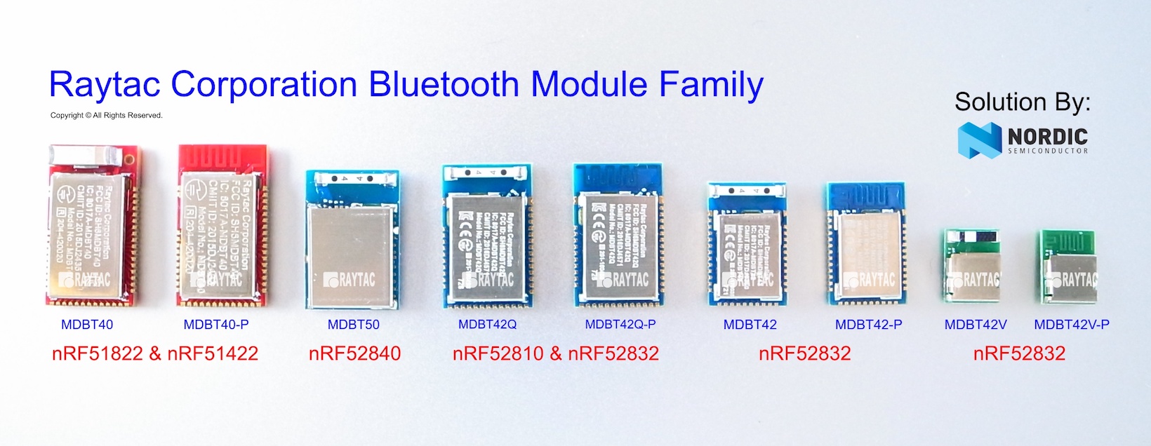
Raytac Corporation 勁達國際電子股份有限公司 / Raytac Corporation (USA) / abietec Inc. A Bluetooth, Wi-Fi, and LoRa Module Maker/ODM & OEM Manufacturer based on Nordic nRF54; nRF53: nRF52; nRF51; nRF7002 Infineon: CYW55912 NXP: RW610, RW612 Semtech: SX1262
Bluetooth Specification: BT6 ; BT5.4 ; BT5.3 ; BT5.2. Wi-Fi Specification: Wi-Fi 6 LoRa Specification: LoRaWAN Zephyr Project Silver Member
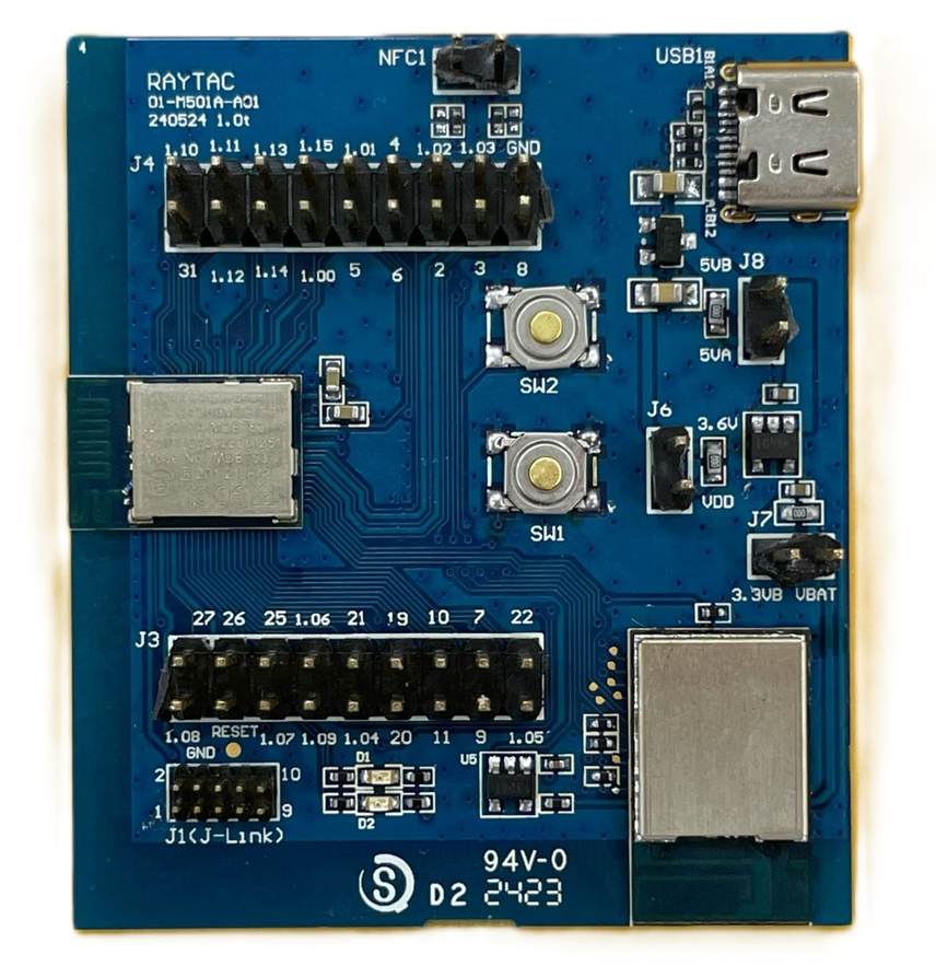
Raytac has advanced the dev kit version of bundle offer – WIFI+BLE: AN7002Q-DB- 5340-M with an on-board flash memory(MX25R64) to create easy evaluation for Wi-Fi project developments.
[January 2026 Update] In this article, we will talk about: Project WITH External Flash MX25R64(8MB) applied – Connecting through SPI between nRF5340 module: MDBT53-1M(BLE) & nRF7002 module: AN7002Q(WIFI) – Connecting through QSPI (XIP) between MDBT53-1M and external memory MX25R64
Table of Content———————————————————————————————————
Hardware Set Up A. Project WITHOUT External Flash MX25R64 needed B. Project WITH External Flash MX25R64 needed
Software Resources & Preparations
Firmware Build & Compile A. Project WITHOUT External Flash MX25R64 needed B. Project WITH External Flash MX25R64 needed
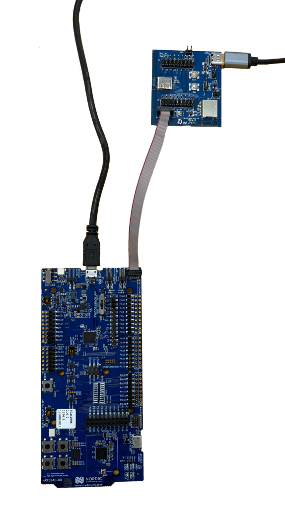
Note: Pease make sure to have both “Nordic nRF5340-DK” and “AN7002Q-DB-5340-M”connected and running during the WIFI+BLE (nRF7002+nRF5340) project development.
Hardware Network: IDC Ribbon Wire(J-Link Cable): Connect nRF5340-DK to AN7002Q-DB-5340-M USB Wire –Type C USB: Power supply to AN7002Q-DB-5340-M through USB TYPE-C USB Wire-Micro USB: Power supply to nRF5340-DK through Micro USB
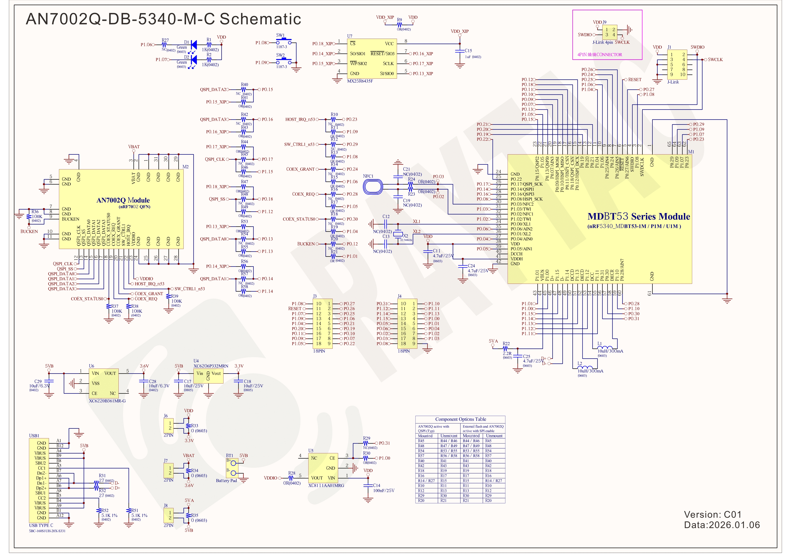
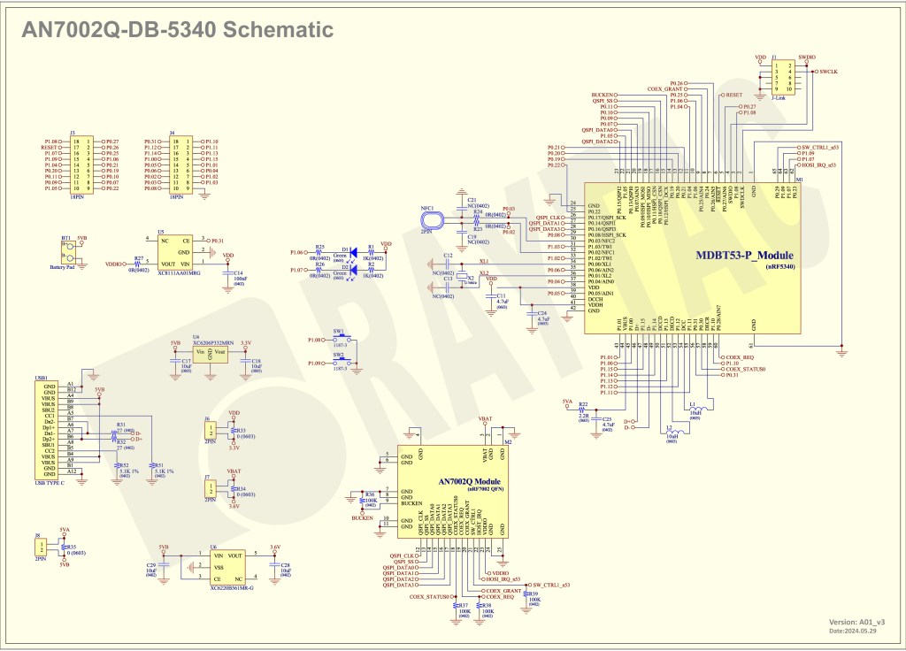
Schematic diagram of AN7002Q-DB-5340-M can be referenced for design as follows. *nRF7002 module <- SPI -> nRF5340 module *MX256R NOR Flahs <-QSPI-> nRF7002 module (Click on the image to zoom in.)
!! Important Note:!! The circuit of SW1(p1.08)/SW2(p1.09)/LED1(p1.06) on AN7002Q-DB-5340-M is NOT COMPATIBLE to Nordic WI-FI Control Pin of swctrl1(p1.08)/host_irq(p1.09)/grant(p1.06). In this case, if you’re working with external flash MX25R64 for the WIFI project, Please avoid pin SW1/SW2/LED1 usage while LED2(p1.07) remains available as normal usage. For the PCB design of end product/end device(mounted with AN7002Q & MDBT53 modules), the switch & LED should be configured to be: SW1(p0.23)/SW2(p0.24)/LED1(p0.28).
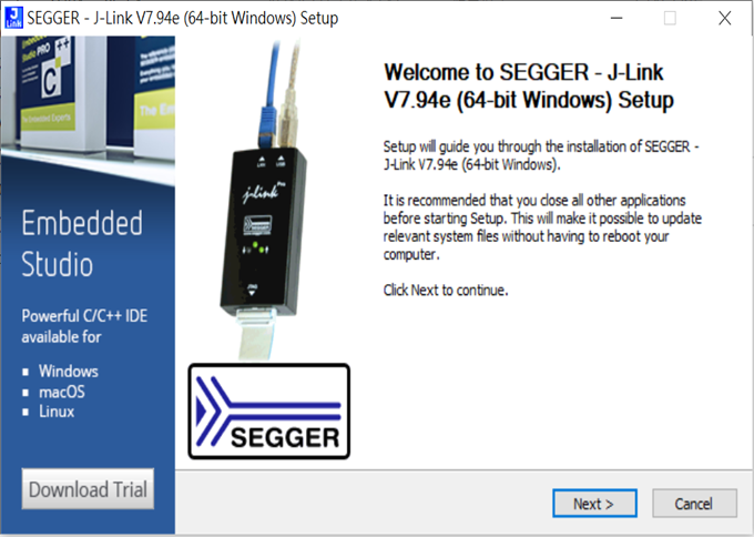
Step 1: Prepared with the latest version of nRF Connect for Desktop, using Windows 64-bit – 5.2.0 Step 2: Prepared with the latest version of Command Line Tools, using Windows X86 64 – 10.24.2
**Note: SEGGER J-LINK Upgrade message might pop up while you’re doing above downloads.
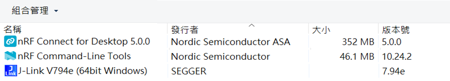
Step 3: Locate all the necessary kits for programming in PC
3. Firmware Build & Compile After you download and set up nRFConnect SDK (NCS), you will be able to apply free VS (Visual Studio) Code IDE as firmware programming tool.
The below example uses NCS v3.1.1 and runs the program under: C:\ncs
Step 1: Start with a Wi-Fi Scan project and run the program under: C:\ncs\v3.1.1\raytac <<Create a new application and Copy a sample>>
Step 2: Select SDK v3.1.1 to copy the sample
Step 3: Select example by entering keyword: wifi scan(Wi-Fi Scan)
Step 4: Enter application location: C:\ncs\v3.1.1\raytac and name the project as: wifi_scan_uart_dfu
Step 5: Open an existing application and find the registered project: wifi_scan_uart_dfu
Step 6: How to activate the Devicetree setting of Wi-Fi nRF7002 and Create file:nrf5340dk_nrf5340_cpuapp.overlay Code example is as follows: / { chosen { aliases { /delete-node/ leds; /delete-node/ buttons; }; };
Step 7: It is required to do MCUBoot before working with DFU using External Flash Please do the code configuration in sysbuild.conf as following reference code.
SB_CONFIG_BOOTLOADER_MCUBOOT=y # DFU with UART SB_CONFIG_MCUBOOT_MODE_SINGLE_APP=n
# DFU with external flash SB_CONFIG_PM_EXTERNAL_FLASH_MCUBOOT_SECONDARY=y
Step 8: It is required to doMCUMGR before working with DFU over UART Please do the code configuration in prj.conf as following reference code.
# Enable QSPI driver for Application CONFIG_NORDIC_QSPI_NOR=y
# Enable mcumgr DFU in application CONFIG_MCUMGR=y CONFIG_NET_BUF=y CONFIG_ZCBOR=y CONFIG_CRC=y
# Enable mcumgr management for both OS and Images CONFIG_MCUMGR_GRP_OS=y CONFIG_MCUMGR_GRP_IMG=y CONFIG_FLASH=y CONFIG_IMG_MANAGER=y CONFIG_STREAM_FLASH=y CONFIG_FLASH_MAP=y
# Configure MCUMGR transport to UART CONFIG_MCUMGR_TRANSPORT_UART=y CONFIG_BASE64=y
Step 9: Add with MCUBoot setting , and create a root for sysbuild ; Build with file mucboot.overlay & file mcuboot.conf
9A. To the File: mucboot.overlay &mx25r64 { status = “okay"; };
Step 10: Create a VERSION file by referencing the following code when testing DFU over UART. VERSION_MAJOR = 99 VERSION_MINOR = 0 PATCHLEVEL = 0 VERSION_TWEAK = 0 EXTRAVERSION =
Step 14: Generate a Merged.hex file after compiling the program
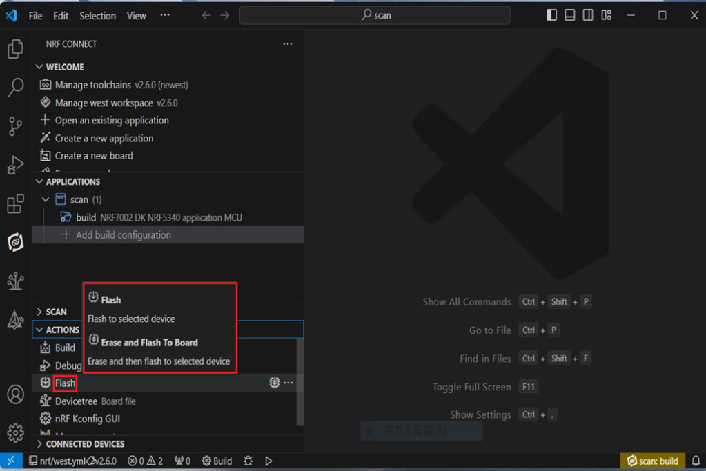
Step15: You can choose Build/Debug/Flash under ACTIONS during development << Build >>
<< Debug >>
<< Flash >>
Step 16: Go to ACTIONS >> Memory report to check the memory partitions.
Now you can see partitions available in the system. mcu_secondary has already been located in MX25R64 flash memory.
4. Test/Validate DFU Process & WIFI SCAN After the firmware programmed to MDBT53 module on board, we use the USB to UART adaptor board for connecting AN7002Q-DB-5340-M through: A. MCUMGR UART to PC and through: B. WiFi Scan UART to PC respectively. Note: We suggest you finish connecting A. and B. before running tests.
Now we can run the tests.
A. DFU over UART – Using AuTerm Program 1. We can locate Image version=V99.0.0 under the current VERSION file
It also indicates Image version: 99.0.0 in MCUmgr-Slot 0.
2. Try to modify the file version from V99 to V100 under VERSION file: VERSION_MAJOR = 100
VERSION_MINOR = 0
PATCHLEVEL = 0
VERSION_TWEAK = 0
EXTRAVERSION =
And go with “Pristine Build”
3. We’re about to run DFU over UART , Please DO NOT do “Flash” or “Erase”.
Proceed with “Force reboot”
4. It’s now Version 100.0.0 in Slot 0 under MCUgr ⭢ DFU over UART successfully done!
Before it was Version 99.0.0 in Slot 1 under MCUgr.
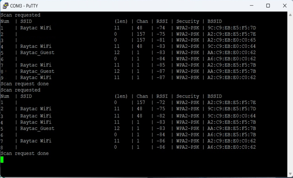
B. WIFI SCAN – PuTTY Console WIFI SCAN credentials can be located under PC Console – PuTTY.
Currently, the Nordic Wifi module – AN7002Q on Raytac’s AN7002Q-DB-5340 board isn’t loaded with a Wi-Fi MAC address. You can choose to use your own MAC address or request one from Raytac. Below is a complete tutorial for users who would like to purchase MAC addresses themselves.
Note: Raytac provides two free Wi-Fi MAC addresses (2.4GHz & 5GHz bands) for each AN7002Q module. If you have a Raytac AN7002Q-DB-5340 demo board but have not received the Wi-Fi MAC addresses, please contact us at sales@raytac.com.
★ What is a MAC Address?
A MAC address (Media Access Control address) is a unique identifier used to identify network devices. It is typically composed of six groups of two hexadecimal digits, for example, 00:1A:2B:3C:4D:5E. The first six characters are known as the Organizationally Unique Identifier (OUI), which identifies the manufacturer or supplier of the MAC address. Manufacturers can use the OUI to identify the producer of the device.
Each network device’s MAC address should be unique. It is an important identifier used for unique identification among network devices, ensuring that devices can communicate correctly within a local area network. However, it is important to note that MAC addresses can be modified within a local network, so they should not be relied upon as the sole basis for security.
★ How to Obtain a MAC Address?
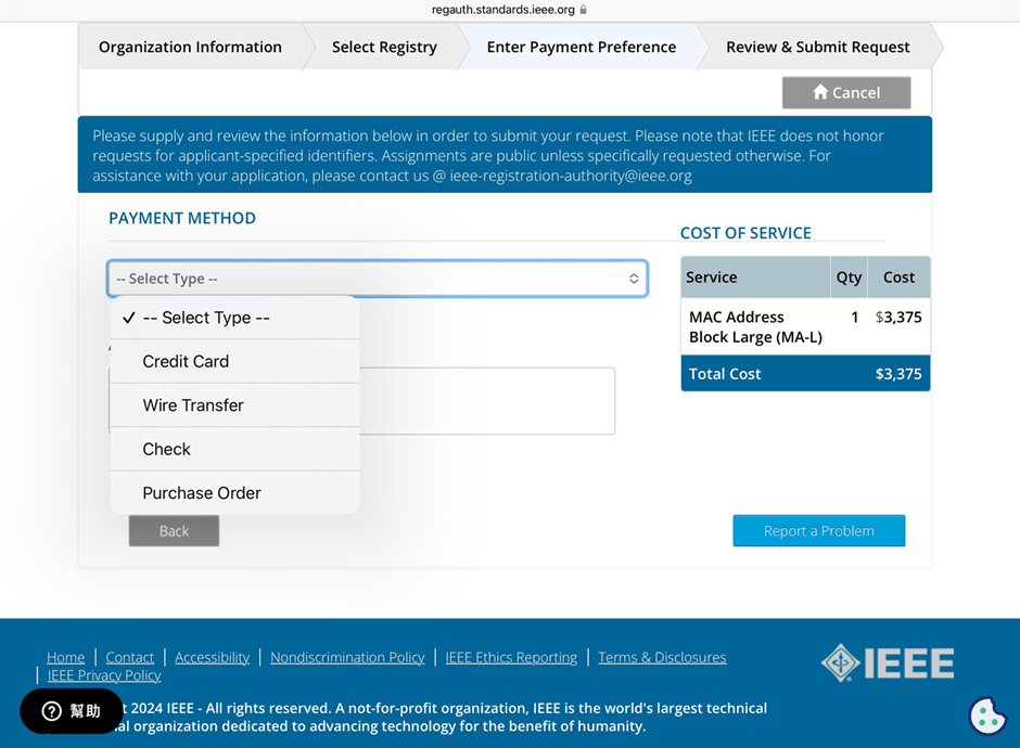
The application and distribution of MAC addresses are managed by IEEE (Institute of Electrical and Electronics Engineers). Here’s how to apply for a MAC address from IEEE: Currently, MAC addresses can only be purchased directly from the IEEE Standards Association in the United States. Depending on the quantity, they can be categorized as:
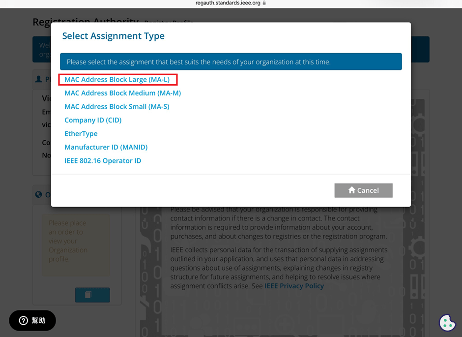
MA-L (approximately 16 million addresses) MA-M (approximately 1 million addresses) MA-S (4096 addresses)
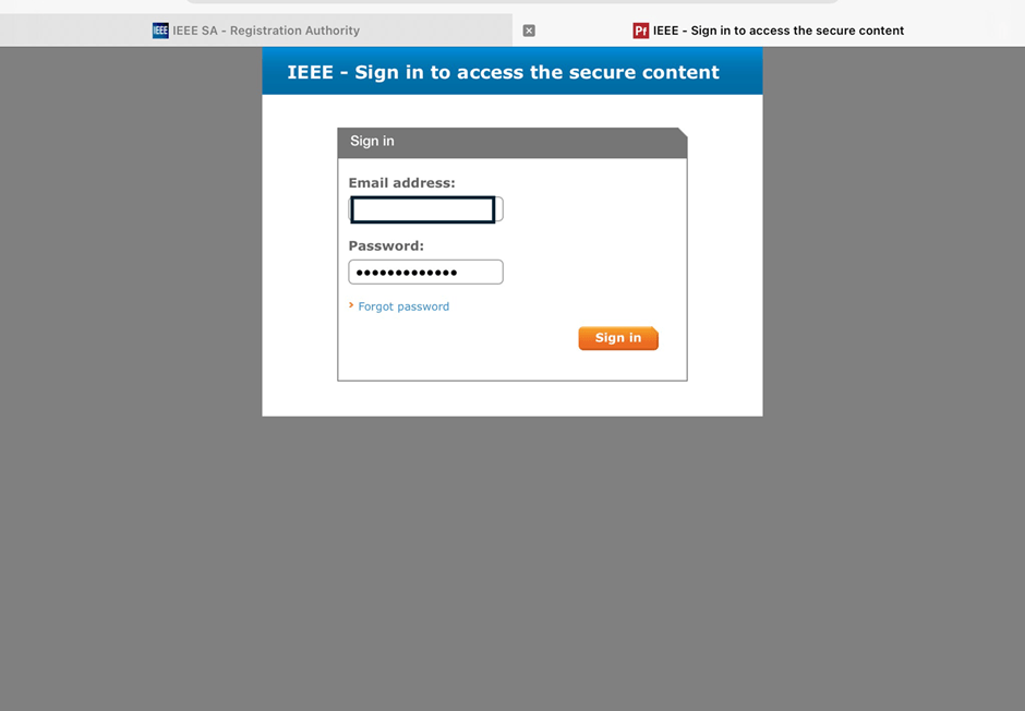
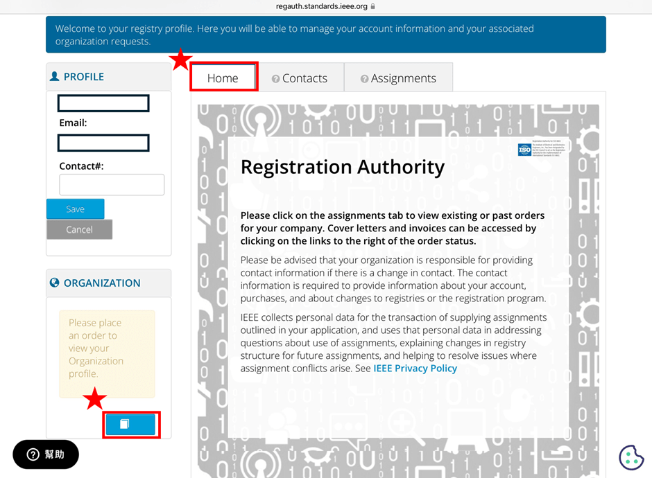
2. Log in and go to the MAC Address Purchase Page After logging in, navigate to the MAC address purchase page:IEEE MAC Address Purchase
3. Select the number of MAC Addresses to purchase.
4. Fill in your purchase information by providing the required details.
5. Confirm confidentiality Confirm whether the MAC address purchase is confidential. If you are purchasing publicly registered MA-L, select “No" for this option.
6. Choose payment method IEEE accepts several payment methods, including mailing a U.S. bank draft, wire transfer in U.S. dollars, and online credit card payment.
7. Receive your OUI Within 7 working days, IEEE will send an email to the registered email address containing the purchased OUI.
After obtaining the OUI, you can retrieve all the purchased MAC addresses using code and then import them into a database or Excel for management.
Edited by Sales Manager: Ms. Vicky Huang
Raytac Corporation 勁達國際電子股份有限公司 A Bluetooth, Wi-Fi, and LoRa Module Maker based on Nordic nRF54; nRF53: nRF52; nRF51; nRF7002 Semtech Specification: SX1262
Recently we have received the FAQ: how to write MAC address into the OTP memory of Raytac’s AN7002Q-P Nordic Wi-Fi module? In this article, we’ll get this question explained to give customers a more smooth experience using the AN7002Q-nRF5340 Demo Board(AN7002Q-DB-5340).
Is there an existing Wi-Fi MAC address in the AN7002Q part on the DevKit?
Currently, the AN7002Q module on Raytac’s AN7002Q-DB-5340 board has no Wi-Fi MAC address.
When running Wi-Fi Scan code/Station code/Shell code…etc. on NCS v2.6.0 (and later versions), the AN7002Q module must have a programed Wi-Fi MAC address to function properly.
Therefore, it’s necessary to follow the below process: 1. Program the original Wi-Fi radio test code (..\nrf\samples\wifi\radio_test) into the MDBT53 section, 2. Then write the Wi-Fi MAC address in to the AN7002Q section(nRF7002 IC) via command.
After this, program the original Wi-Fi Scan code/Station code /Shell code … into the 5340, and it will function properly.
**Raytac will assign 2 Wi-Fi MAC addresses(for both 2.4GHz & 5GHz) to every AN7002Q module. *If customers don’t have Wi-Fi MAC addresses for DevKit development yet, please reach out to service@raytac.com
Scenario: Following error occurred when building the SCAN example code, flash it onto the AN7002Q-DB-5340 board, and run the test.
Solution:
When running Wi-Fi scan code on NCS v.2.6.0 or later version, the OTP memory in the AN7002Q module must have a Wi-Fi MAC address programmed in for the Wi-Fi scan functionality to work properly.
(Note: OTP is a One-Time programmable memory, which means the value can only be written once. The customer must aware of this before performing the OTP operation.)
1. Program the original Wi-Fi radio test code (..\nrf\samples\wifi\radio_test) into the MDBT53 section, then manually input and execute the following OTP read command.
wifi_radio_ficr_prog otp_read_params
If you see both MAC0 and MAC1 display a value of 0xFF, as shown in above, it means that you haven’t written the Wi-Fi MAC address into the AN7002Q’s OTP.
2. Manually issue the OTP write command to write the Wi-Fi MAC address into the OTP.
After you complete the above, use the OTP read command in below to check if the Wi-Fi MAC address value was written. The MAC0 and MAC1 should display the value you’ve input from the OTP write command.
wifi_radio_ficr_prog otp_read_params
3. Program the original Wi-Fi SCAN code back into the MDBT53, the Wi-Fi scan functionality should work properly.
To help you quickly get started with Raytac’s AN7002 Nordic WiFi module and nRF5340 module, here’s a simple guide on how to set up the development and programming environment using AN7002Q-nRF5340 Demo Board(AN7002Q-DB-5340)and nRF5340 DK.
This article will cover the 4 sections below: 1. Hardware setup 2. Software Development Kit and Environment setup 3. Programming/Development 4. Flashing/Uploading firmware
1. Hardware Setup 1 x Nordic nRF5340-DK: PCA10095(2.0.0) 1 x Raytac AN7002Q-DB-5340 1 x IDC Cable 1 x USB-Micro USB Cable 1 x USB-Type C USB Cable
*Note: You need to use both the “Nordic nRF5340-DK” and “Raytac AN7002Q-DB-5340 demo board” together for programming and development. *
Steps to connect the hardware:
Connect J-Link on Nordic DK to AN7002Q-DB-5340using IDC Cable
After the installations are completed, you can see the following applications under the:
“Programs and Features" section in the Control Panel.
3. Programming/Development
nRF Connect SDK (NCS) supports development using the free VS (Visual Studio) Code IDE. Here’s how to select and install the NCS SDK version (nRF Connect SDK vx.x.x):
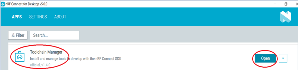
Step1.
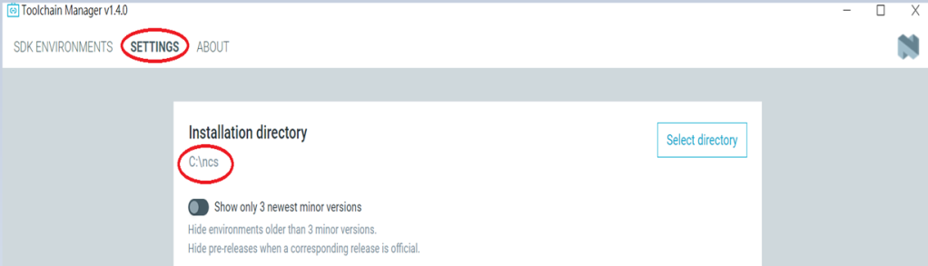
Open “nRF Connect for Desktop” → Choose “Toolchain Manager” → then click” Open”
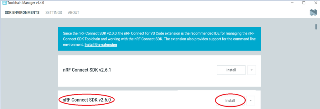
Step2.
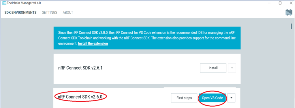
You’ll see a list of nRF Connect SDK versions. It’s recommended to install NCS v2.6.0 or later. Here, we use NCS v2.6.0 as an example.
Step3.
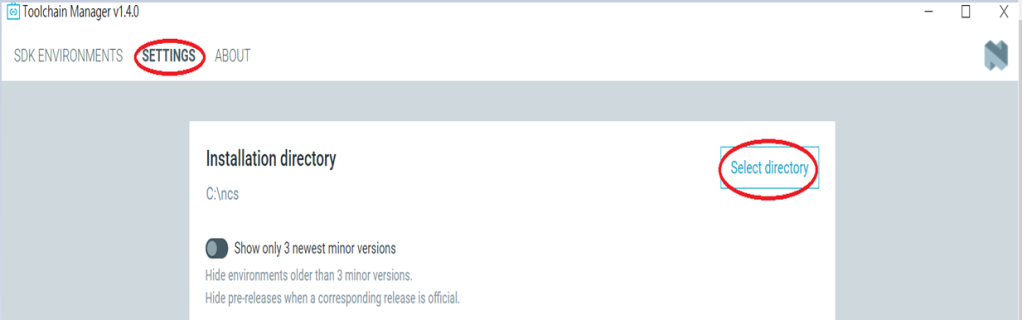
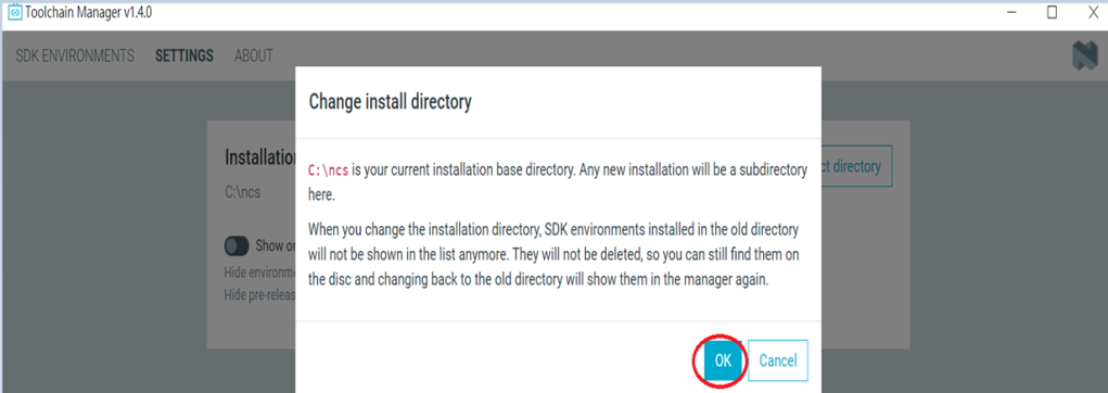
Before installing NCS v2.6.0, confirm the installation path (Default path → C:\ncs).
If you want to change the path, click “Select directory”, and press OK.
Step4.
After installing the nRFConnect SDK v2.6.0, click “Open VS Code”.
Step5.
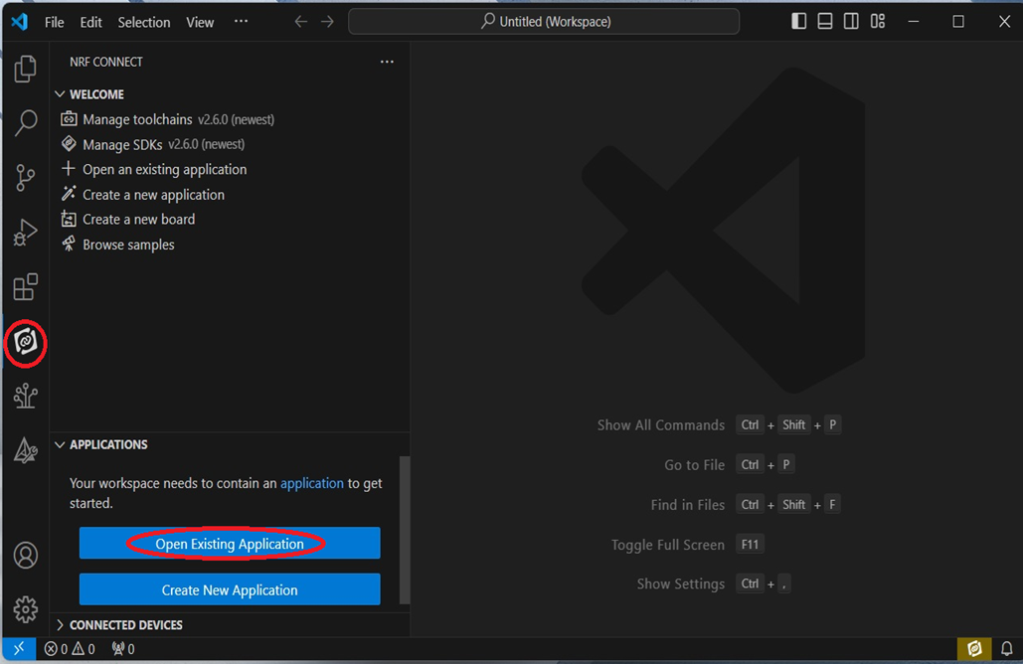
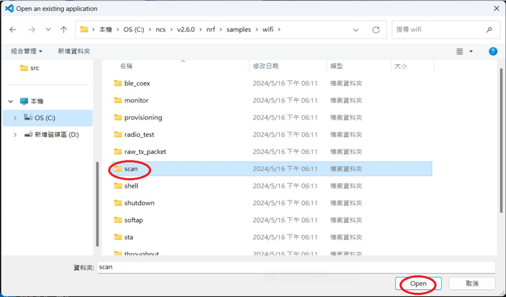
Open the Wi-Fi scan example
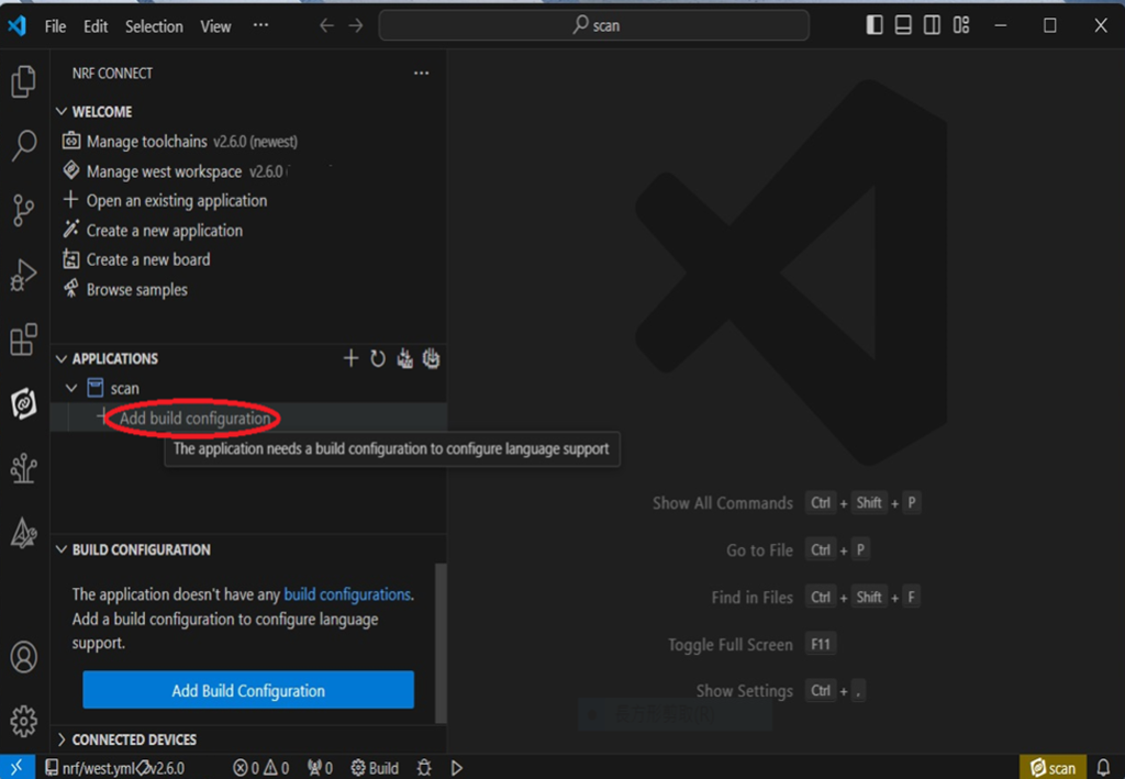
Step6.
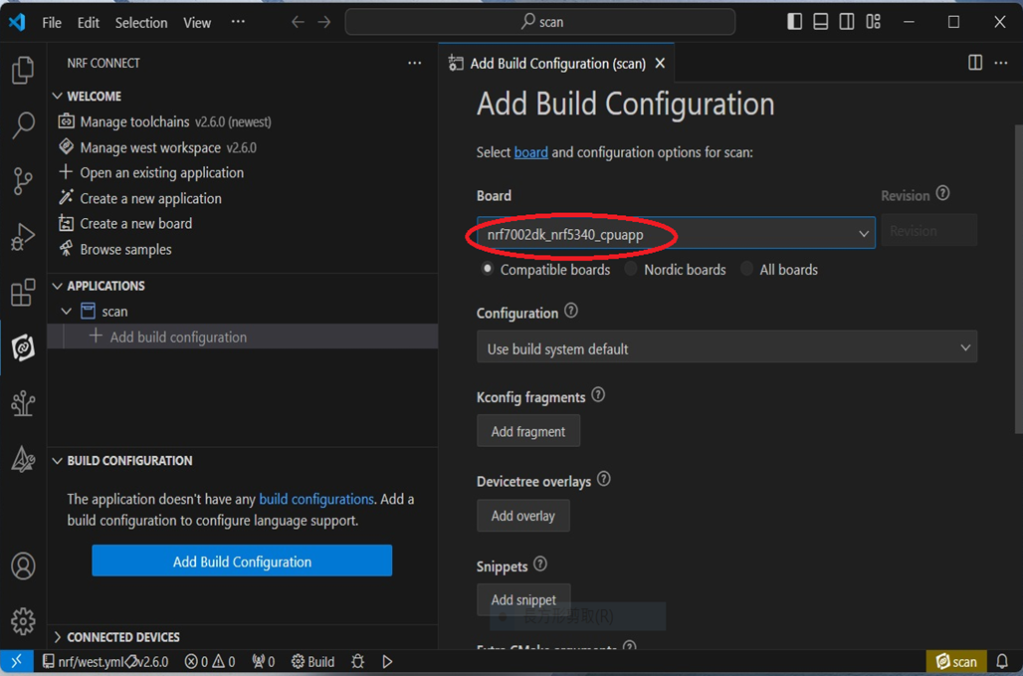
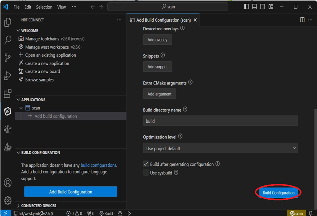
Add build configuration → select the board and compile.
Select board: nrf7002dk_nrf5340_cpuapp.
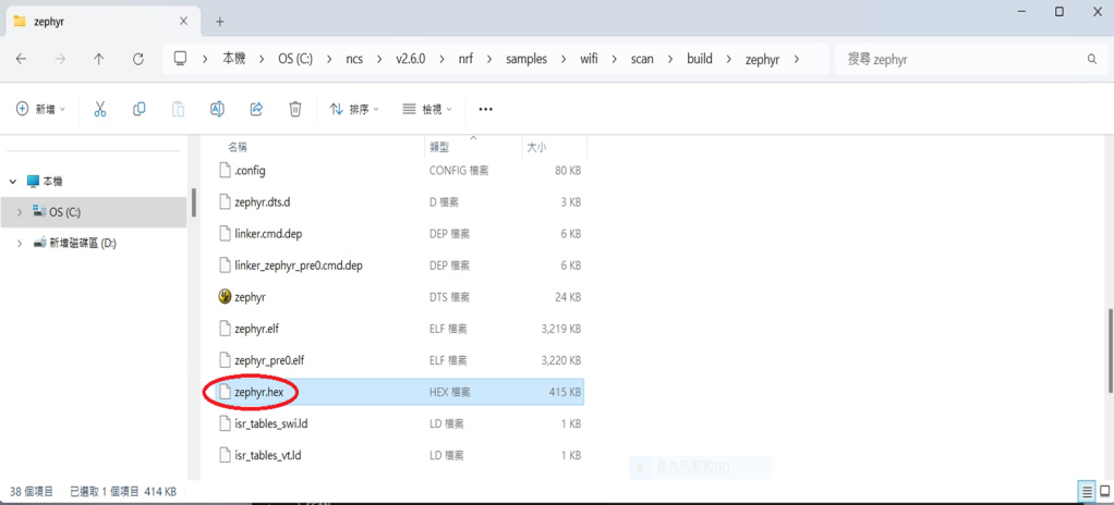
Step7.
After compilation, a hex file will be generated.
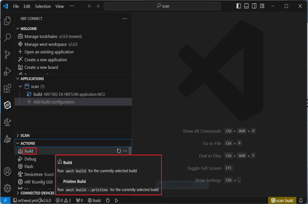
Step8.
Under ACTIONS, you can choose to Build, Debug, or Flash.
Build:
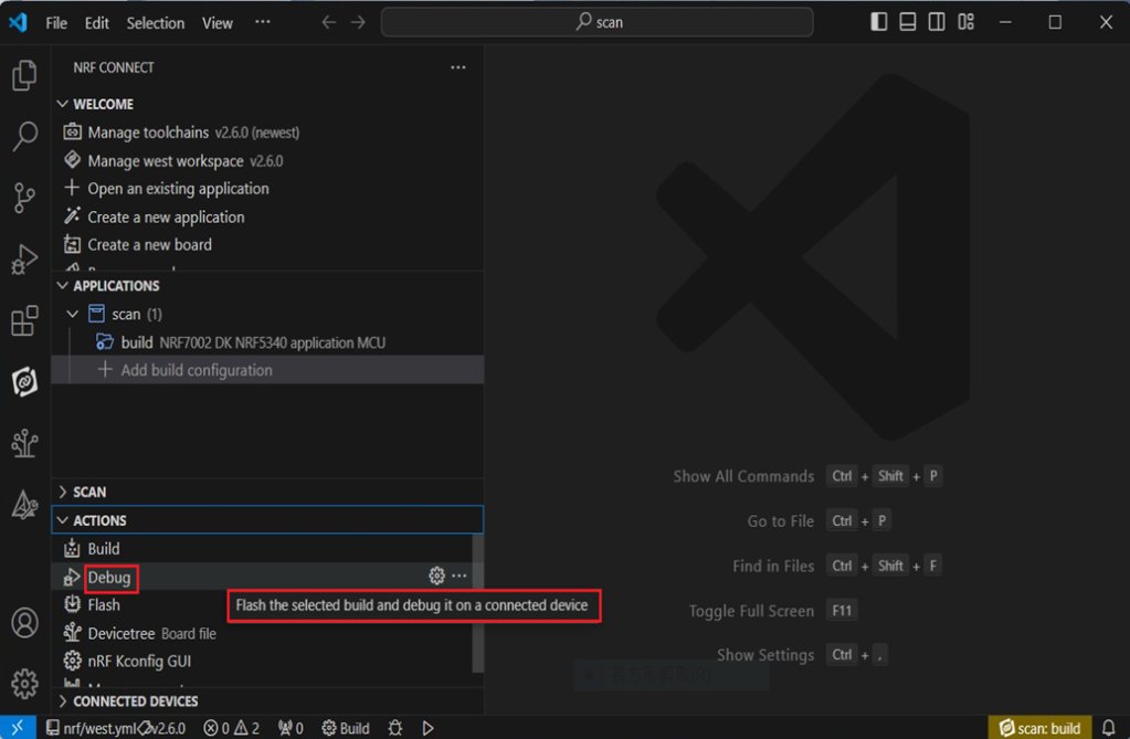
Debug:
Flash:
4. Programming
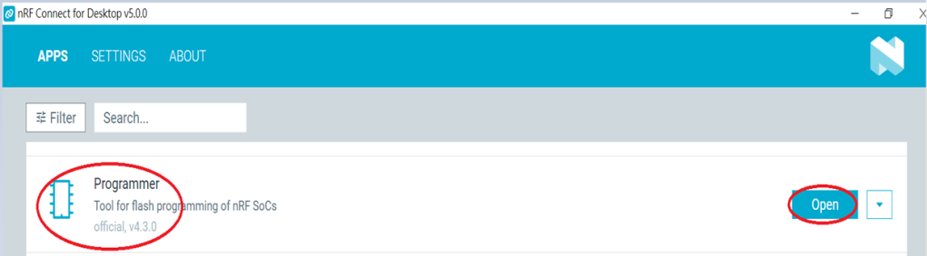
nRF Connect SDK(NCS) supports programming. You can use the “Programmer” tool to flash .hex file. Here’s how:
Step1.
Open “nRF Connect for Desktop” → Select “Programmer” → then click” Open”.
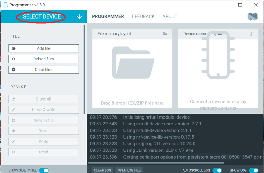
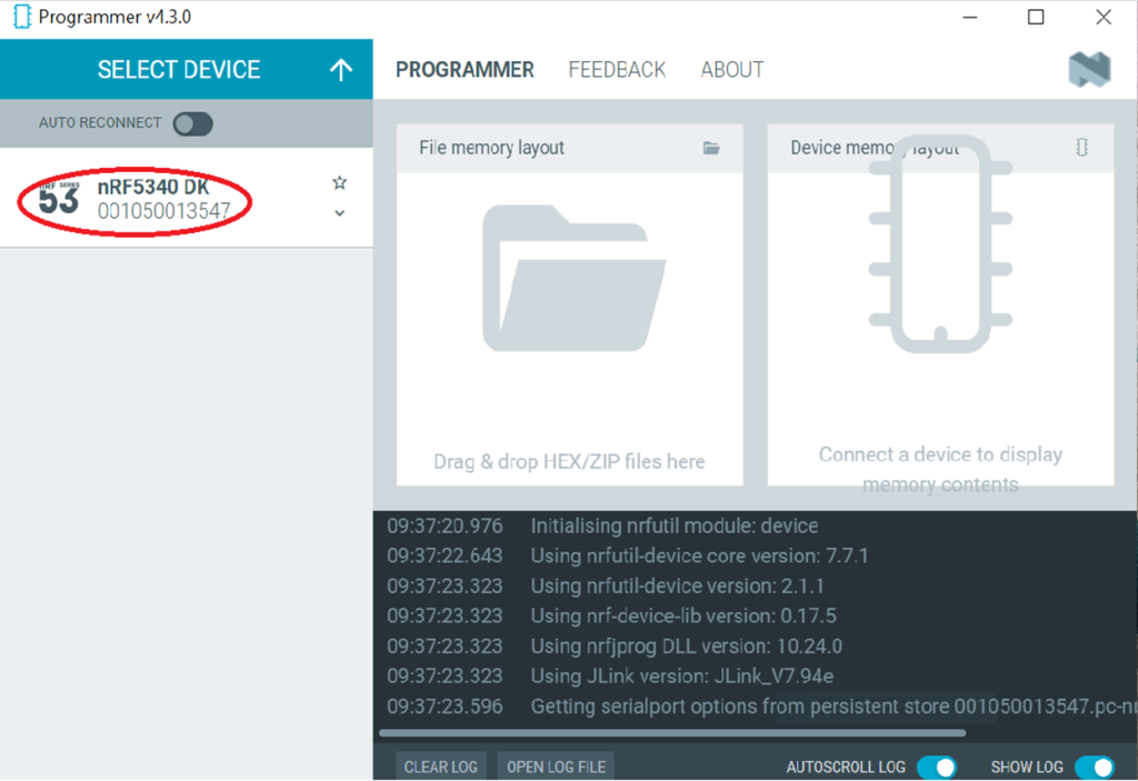
Click “Select Device”;
Since AN7002 Wi-Fi IC does not act as an MCU, we can only flash the .hex file into the MDBT53(nRF5340) BLE IC.
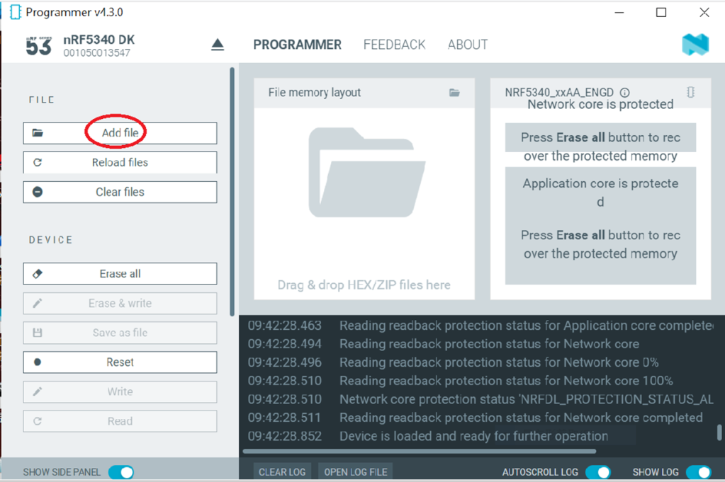
Click “Add file” to add the .hex file.
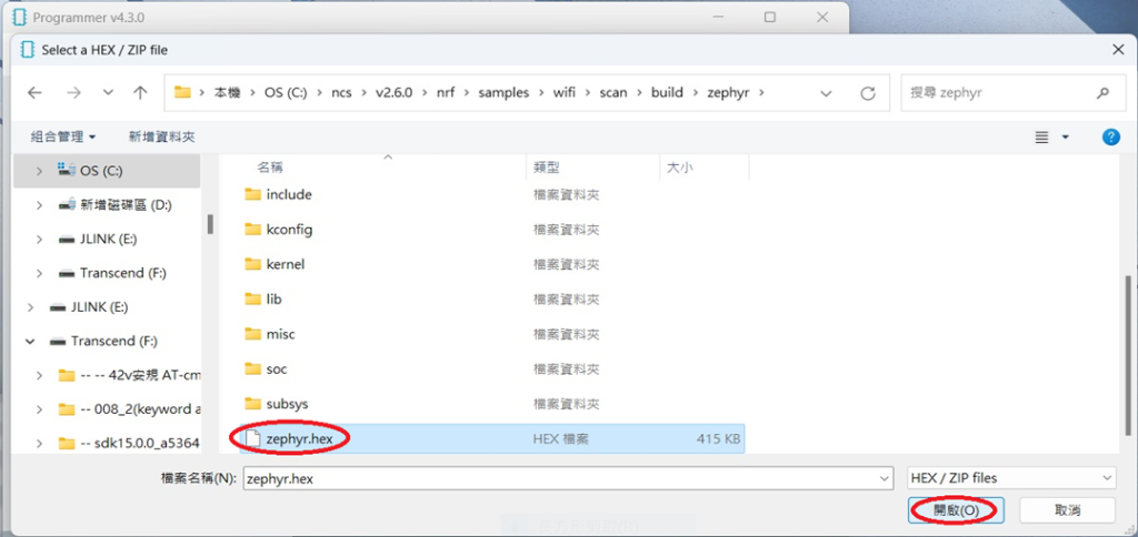
Step2.
Select the .hex file you want to flash.
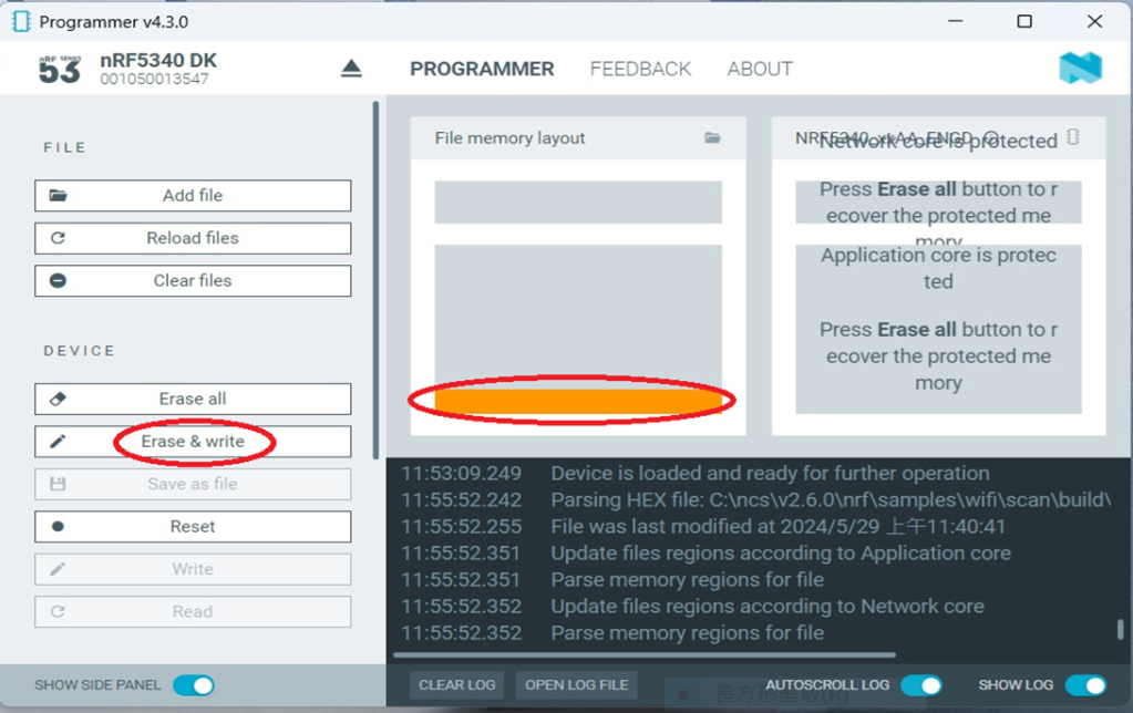
The hex file will be written into the part of the memory layout (where orange part is highlighted).
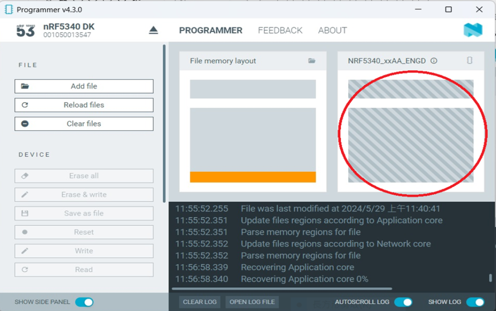
Slashes will be displayed in the circled part during the flash process.
Step3.
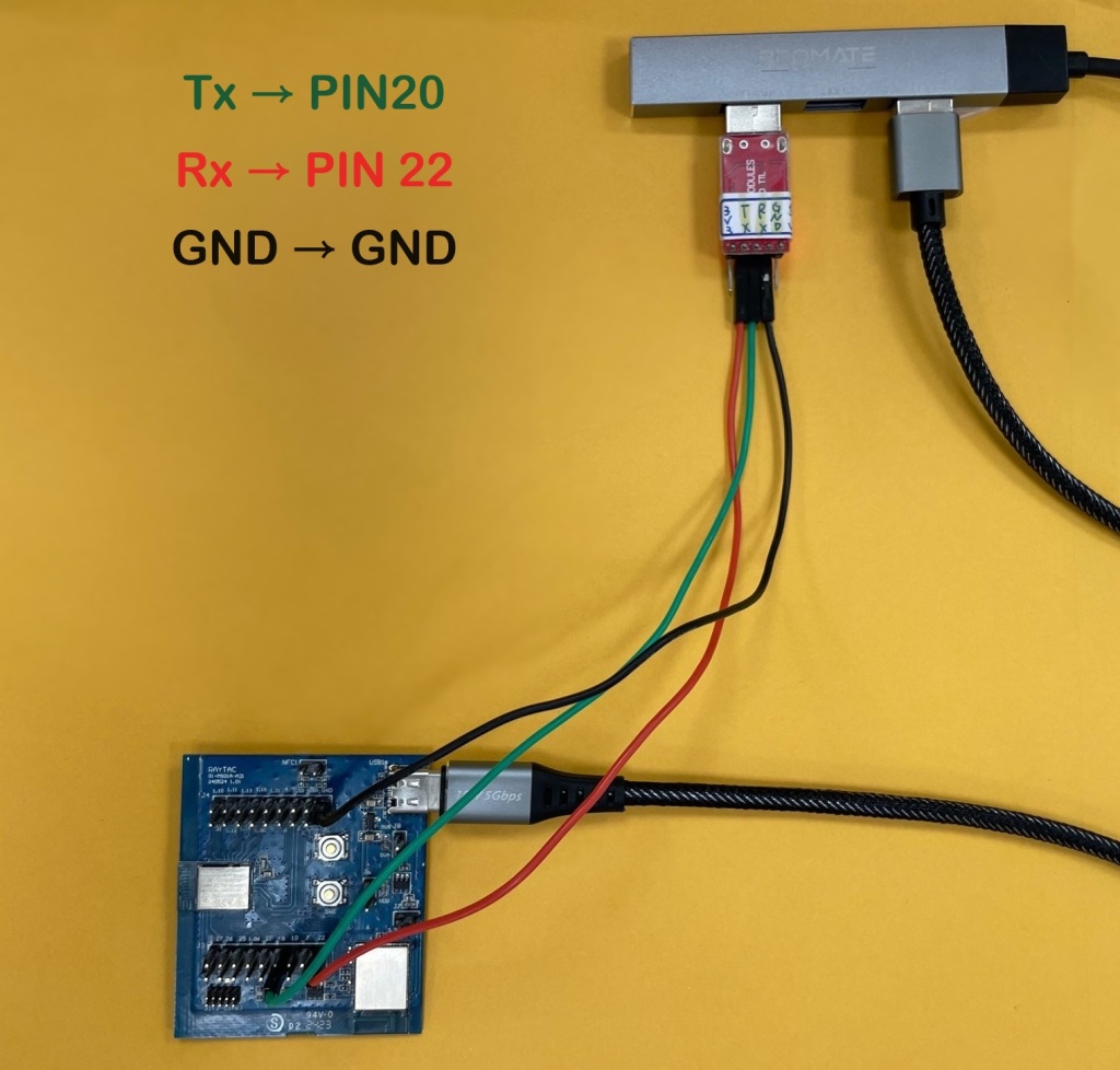
Once the flash process is completed, connect Raytac’s AN7002Q-DB-5340 development board to PuTTY.
Tx to p0.20
Rx to p0.22
GND to GND
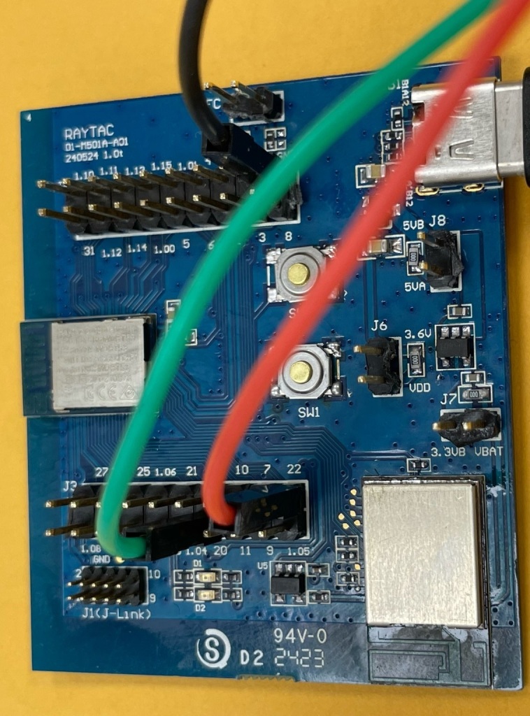
This is a closer look into the pins that will be connected.
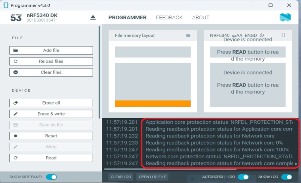
The flash process is completed when the LOG is displayed as circled below.
Check if hardware connection is successful using PuTTY.
*2024-Aug-12 update:* Before running Scan code / Station code / Shell code: You must ensure that the MAC address has already been programmed into the module. Click on this link to learn more about how to load the MAC address.
Edited by Sales Manager: Ms. Vicky Huang Technical guidance provided by R&D Manager: Mr. MW Lee Hardware environment provided by Hardware Engineer: Mr. Kyle Wang
Today, Raytac would like to present an engagement module “MDBT42V”, a compact nRF52832 module (8.4mm x 6.4mm x 1.5mm), built by Nordic solution with Bluetooth Specification BT4.2 & BT5 to all prospective partners.
Mesh Network is future of IoT, also an issue that raised most interests among developers.
With the official Bluetooth Mesh nearing release by SIG, Nordic offers nRF Connect Mesh to provide a solid tools for developers to create mesh-enabled projects.