Easy! At least when you know what to do. Many of our customers just want a device that provides Bluetooth technology to their product or solution that they’ve developed. However, utilizing the full capacity of the Bluetooth protocol is not always easy and sometimes not even necessary. For these customers, choosing Raytac’s modules/dongles loaded with AT Command, such as
MDBT50Q-RX-ATM, is the best choice.
But even a product such as
MDBT50Q-RX-ATM that is supposed to make it easy for customers to wirelessly transfer data from one device to the next can be difficult to use – especially when you don’t know
HOW.So, I thought we’d take this in two simple steps.
- Device Name
To be really sure that you can connect to the device thus making you able to pair with it, you will have to make sure that the device name setting in the AT Command list is set to the name you want or need.
For example, if you have a device set to have the name “I_love_Bluetooth" and you haven’t changed the settings in the AT Command, you will not be able to pair your MDBT50Q-RX-ATM with this device.
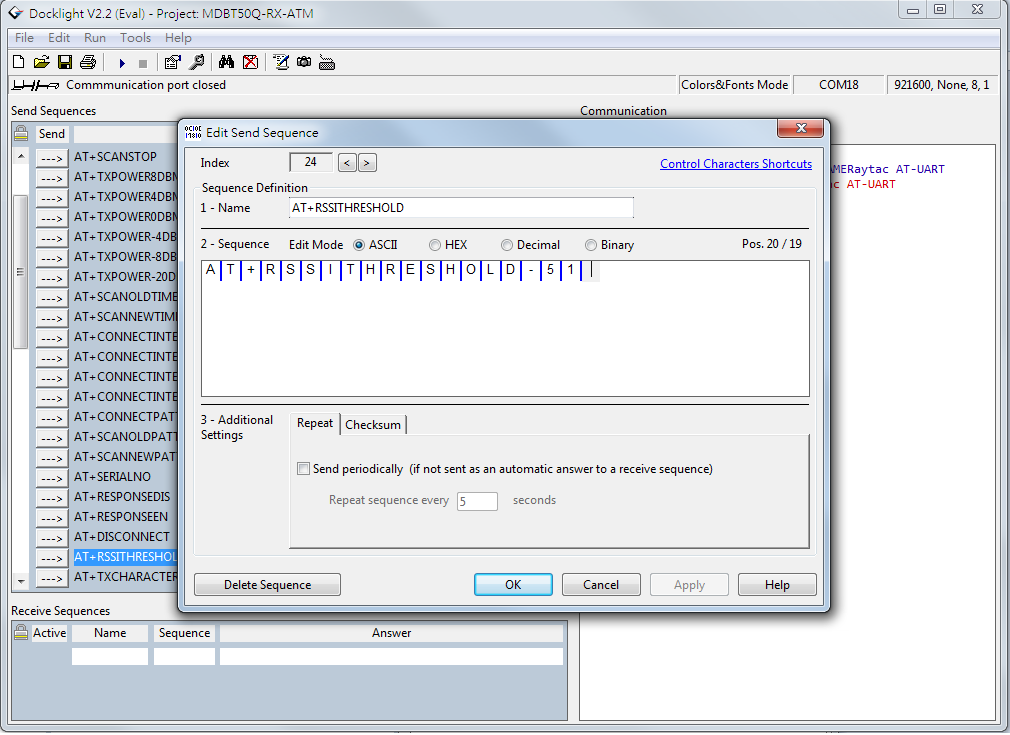
As you can see in the picture below, the default setting for this device’s name is “Raytac AT-UART".

When editing this name, you get a smaller window like this popping up:

Make sure that the name set on your device that you wish to connect with the dongle AND this name in the AT-Command device’s list are the same.
- RSSI
This is a trickier part – especially when you don’t know what it is.
RSSI stands for Received Signal Strength Indicator and, just like the name implies, is a value of strength of which the incoming signal has to be in order to even be considered by the scanning device.
In other words, the lower the value is set to, the weaker signals the scanning device will show.
The standard value of Raytac’s AT-Command modules/dongle is -51 and the setting screen looks like this:
- Slave device’s SDK
What many new customers seem to believe is that if you use our AT-Command modules/dongles, you won’t need to do anything – they will just magically communicate with each other somehow.
I hate to break it to you, but no… that’s not how it works. You will have to at least make sure that the two devices “speak the same language". As for our AT-Command modules/dongles, or in this case MDBT50Q-RX-ATM, it is through a “language" (a.k.a. protocol) called UART.
First of all, “UART" is not “U-ART" although it’s kind of pronounced that way, but it’s an abbreviation that stands for Universal Asynchronous Receiver/Transmitter. You can read about it here.
I will spare you all the details about the UART protocol itself, but one thing that we will need to make sure of is that you have it installed onto your slave device.
Hopefully, you’ve downloaded Nordic’s latest SDK and you have it ready on your computer. You can download them directly HERE.
Note: This file is quite big (~130MB), so DO NOT click on the last link if you don’t want to download this on your current device.
Inside this file, you will find a lot of stuff. However, for this particular case, we only really need to care about the “examples" folder.
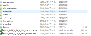
In this folder, we will have (surprise surprise!) even more folders 😀
As per usual, we don’t have to check them all out. In this case, we specifically only want to check the “ble_peripheral" and the “peripheral" folders.

Go into the former folder and you’ll find see the following folders in which you will want to enter the “ble_app_uart" folder.:

In this folder, you will see five more folders and two files, but we only want to check out one of them depending on which chip type you’re using in your slave device. Let’s say you’re using a nRF52832 chip (or module such as MDBT42Q-P512KV2), then you’d want to enter the first folder called pca10040. Check the picture below to see which folder you’d want to enter:
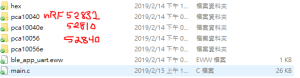
Assuming you entered the folder that I mentioned above, you will then want to enter the “s132″ folder.

Once you’re in here, I am pretty sure you developers out there know what to pick 🙂
In the beginning of this section, however, I also mentioned another folder called “peripheral" which we will guide you through now – even if it’s very similar to what we just did.

As you can see, there are a TON of folders in here, but we will cherry-pick our folders here too.
Let’s say that you’d like to be able to make your slave device to read and transmit information from a sensor. Supposedly, most sensors use either the I2C or the SPI interface. In each respective folder, you will find the same folder layout as in the previous picture – folders representing what chip/module you have.
The main point of showing you this is simply because from these two folders, you can snatch the small amount of code that you need to edit the main code of your UART main-code so that you can both read and send the data from the sensor you might have.
Hopefully, you’ve now started to realize how these things come together and we can finally start to connect these devices. This takes us to the next step:
- ATSCANNEW
Once that’s done, you will need to use your AT-Command module/dongle (here MDBT50Q-RX-ATM) to scan for the slave device that you want to pair. To do this, you first have to make sure your slave device is broadcasting, then execute a command called ATSCANNEW.
Once you’ve done so, your MDBT50Q-RX-ATM’s blue LED will hopefully go from fast blinking to a slower blinking. This means that your two devices, master and slave, have now paired successfully. Wohoo! 🙂
We hope that this makes our AT-Command modules/dongles even easier to use!
Raytac wishes you all happy tinkering 🙂


 Obviously, each and every certification has their own rules, so that’s how we’re going to do this – one by one.


 Now we know

