[CA, USA/Taipei, Taiwan]
Raytac Group, a worldwide leader in wireless modules, wireless solutions, and a Nordic-recommended third-party module manufacturer, is pleased to announce the official release of the AN54LQ-AT and AN54LV-AT series, our newest Bluetooth® Low Energy AT Command modules built upon Nordic Semiconductor’s nRF54L15 ultra-low-power wireless SoC.
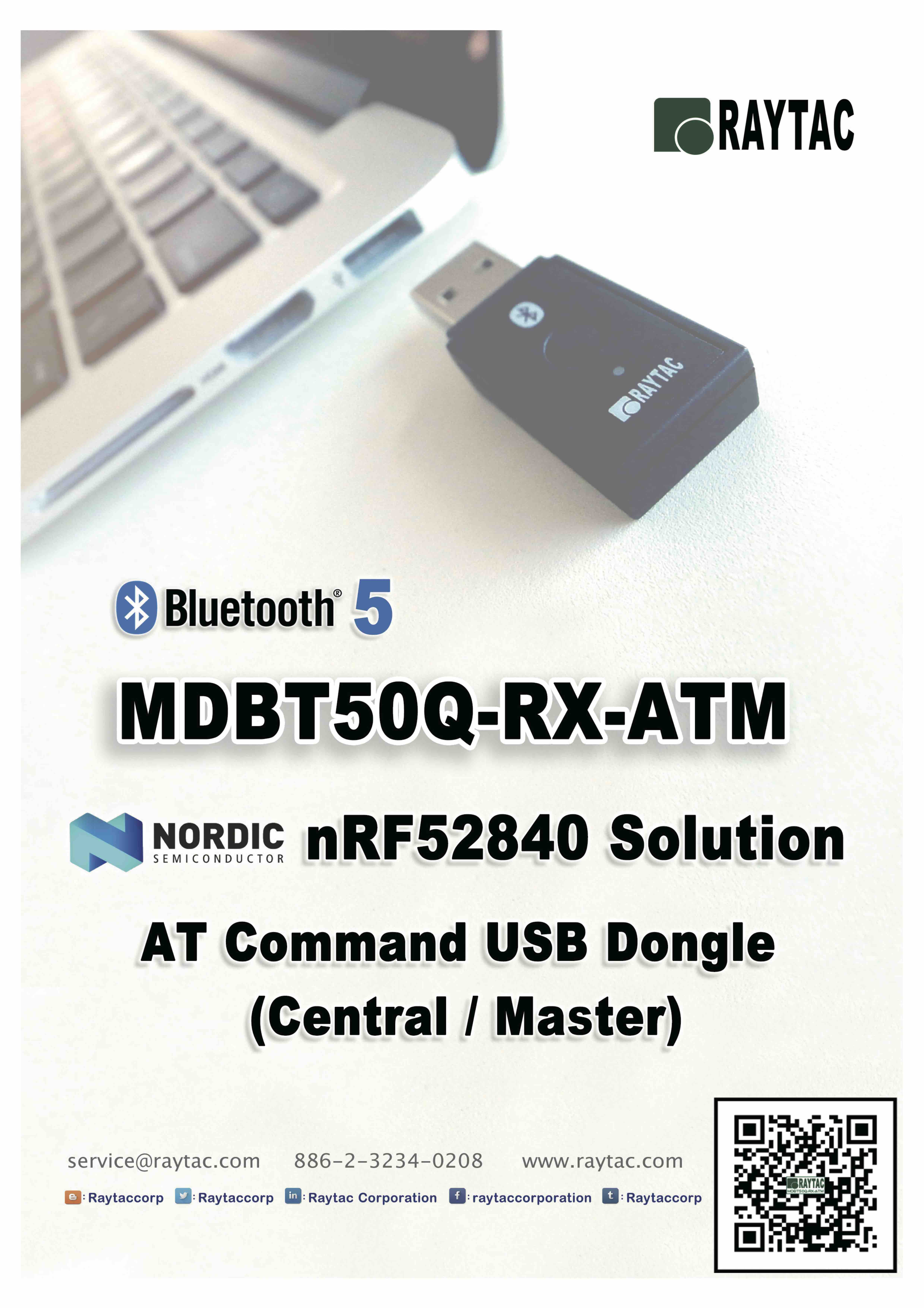
Designed for engineers who want to integrate BLE quickly and easily, the AT Command series comes with pre-loaded peripheral (slave) role firmware, enabling straightforward UART communication with a host MCU through simple AT Commands.
Built on Nordic’s next-generation nRF54L15 SoC, the series delivers exceptional power efficiency, reducing power consumption by approximately 50% compared to previous-generation nRF52-based AT Command modules.
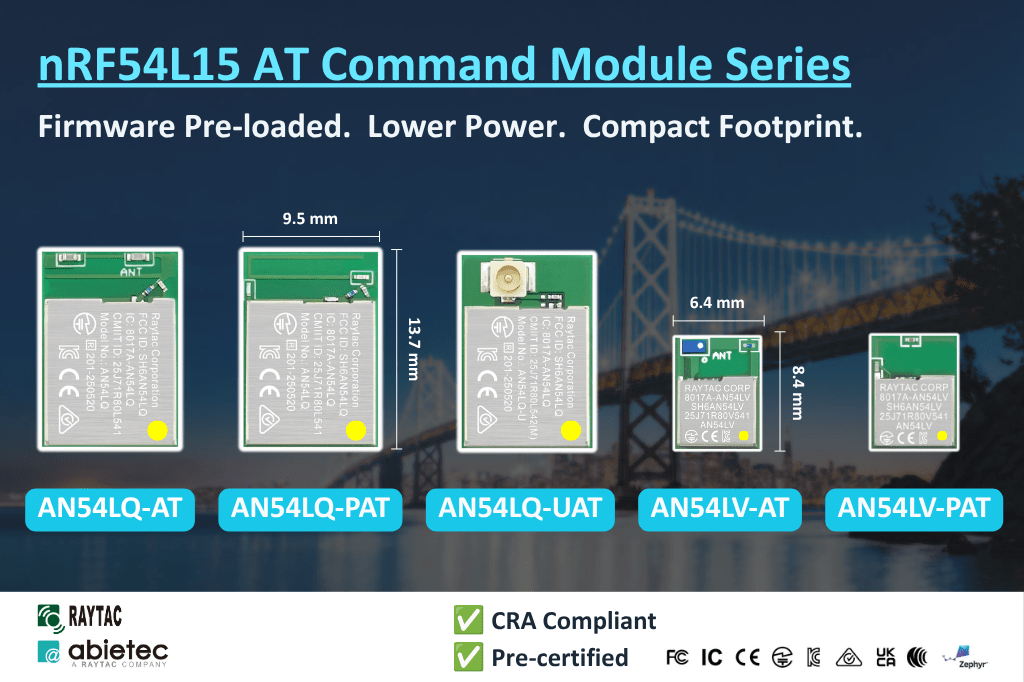
The nRF54L15 AT Command family is available in five variants to satisfy different RF and mechanical requirements.
AN54LQ Series
– Ceramic chip antenna: AN54LQ-AT (Click here for full product details)
– PCB trace antenna: AN54LQ-PAT (Click here for full product details)
– u.FL connector for external antenna: AN54LQ-UAT (Click here for full product details)
AN54LV Series
– Ceramic chip antenna: AN54LV-AT (Click here for full product details)
– PCB trace antenna: AN54LV-PAT (Click here for full product details)
AT Command Development Kit
– AN54LQ Series: AN54LQ-AT-UART-S (Click here for full product details)
– AN54LV Series AN54LV-AT-UART-S (Click here for full product details)
The standard AN54LQ family measures only 9.5 × 13.7 × 1.8 mm, while the AN54LV family further reduces the footprint to just 6.4 × 8.4 × 1.5 mm, making it an excellent choice for wearable devices, portable products, industrial sensors, medical devices, and other space-constrained applications.
Engineers can integrate Bluetooth communication(peripheral role) into an existing MCU platform without implementing the Bluetooth LE protocol or maintaining a Bluetooth LE firmware stack.
Acting as a seamless bridge between the host MCU and Bluetooth devices, the AT Command module enables easy wireless communication without any complexity of firmware development.
Technical Overview
| Category | Specification |
| Series | AN54LQ and AN54LV |
| Antenna Options | Chip antenna, PCB antenna, u.FL (external antenna) |
| Bluetooth® Certification | Bluetooth® 6.0 certified |
| RF Certifications | FCC, IC, UKCA, CE, TELEC (MIC), KC, SRRC, NCC, RCM, WPC |
| Processor | 128 MHz Arm® Cortex®-M33 processor + 128 MHz RISC-V coprocessor |
| Security | Enhanced security aligned with EU Cyber Resilience Act (CRA) requirements |
| Interfaces | UART(Bluetooth Connectivity via UART AT Commands) |
| Key Features | – Rich AT Command(Peripheral/Slave Role) set, No firmware development needed – Up to 50% Lower Power Consumption vs. nRF52-based AT Command Modules – Selectable 1 Mbps / 2 Mbps PHY Data Rate – Custom UUID Configuration (Hex Format) – Built-in Power Saving & GPIO Wake-Up Functions – Advertising/Connection Control – RSSI, Battery Monitoring & Device Management |
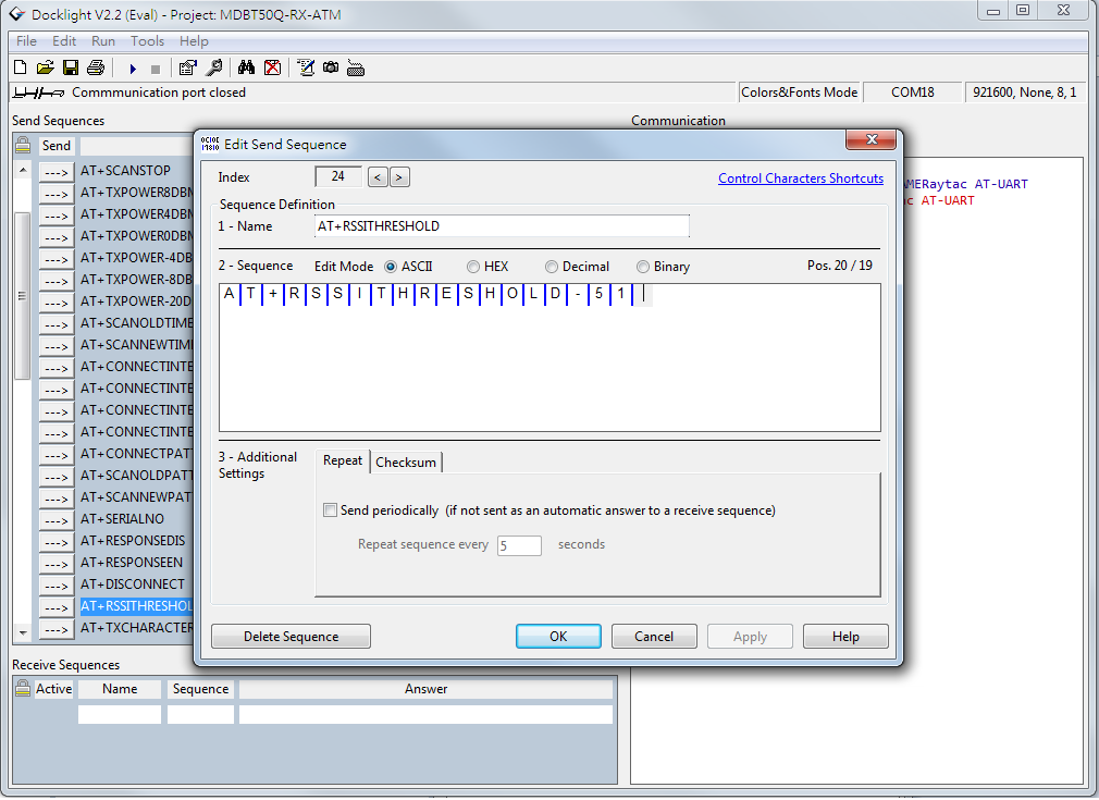
List of supported commands
- Setting of device name
- Choose data rate of 1Mbps or 2Mbps on-air
- Set TX output power in 6 levels.
- Set advertising time
- Set connection interval under Mode 2
- Enable/disable advertising
- 8 sets of UART baud rates
- Enable/disable UART flow control
- Enable/disable interface of UART hardware
- Power-down mode for power saving and GPIO wake-up
- Recover-to-default setting with hardware and software method
- System reset of hardware and software
- Set serial number and retrieve
- Set or retrieve MAC Address
- Retrieve ADC value for battery detection, delivering the information through battery service.
- Enable/disable connection command mode
- Setting of advertising interval
- Retrieve RSSI value of the connected
The modules are already in Mass Production.
Please subscribe to Raytac’s WordPress blog: https://raytac.blog for more upcoming information.
Welcome to send an inquiry to any of the below links:
Raytac Corporation contact form: https://www.raytac.com/contact/
Raytac Corporation mailbox: sales@raytac.com
abietec Inc. contact form: https://www.abietec.com/contact
abietec Inc. mailbox: service@abietec.com
to discuss how Raytac/abietec can support your project.
Let’s keep in touch!
Raytac Corporation 勁達國際電子股份有限公司 / Raytac Corporation (USA) / abietec Inc.
A Bluetooth, Wi-Fi, and LoRa Module Maker/ODM & OEM Manufacturer based on
Nordic nRF54; nRF53: nRF52; nRF51; nRF7002
Infineon: CYW55912
NXP: RW610, RW612
Semtech: SX1262
Bluetooth Specification: BT6 ; BT5.4 ; BT5.3 ; BT5.2.
Wi-Fi Specification: Wi-Fi 6
LoRa Specification: LoRaWAN
Zephyr Project Silver Member
All products are FCC/IC/CE/Telec/KC/RCM/SRRC/NCC/WPC/RoHS/Reach Certified.
Tel: +886-2-3234-0208(TW)/+1-626-328-3827(USA)