User Manual of Raytac AN54LV-DB-15 (Nordic nRF54L15 Module DevKit) Development & Programming Environment

Want to get started quickly with Raytac’s AN54LV-15 module? We provide a simple tutorial to guide you step-by-step through setting up the development and programming environment for the nRF54L15 module Development Board (AN54LV-DB-15) and nRF54L15-DK.

Table of Contents
1. Hardware Environment Setup
2. Software Development Kit Resources and Environment Setup
3. Software/Firmware Application Development
4. Flashing / Programming

Related products:
nRF54L15 SoC Spec  << access link
Nordic nRF54L15 DK  << access link
Raytac AN54LV-DB-15 (Development Kit used in this article) << access link
Zephyr documentation of AN54LV-DB-15 << access link
Raytac AN54LV-DB-U15 (Development Kit with u.FL Connector for external antenna)  << access link
Raytac AN54LV-DB-K15 (Development Kit with antenna pin) << access link

User manual of Raytac AN54LQ-DB-15 << access link

Nordic nRF54L15-DK


1. Hardware Environment Setup
The required equipments are as follows:

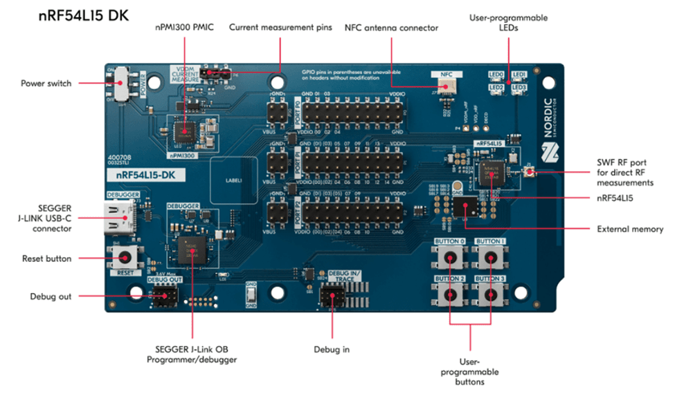
  • 1 x Nordic nRF54L15-DK: PCA10156(1.0.0)
  • 1 x AN54LV-DB-15 (Raytac nRF54L15 module Development Board)
  • 1 x IDC Ribbon Cable
  • 2 x USB Type-C Connection Cables

* Reminder: The “Nordic nRF54L15-DK" and “Raytac AN54LV-DB-15 Development Board" must be used together to proceed with application development and flashing firmware into the Raytac AN54LV-DB-15 development board.

Setup Steps:
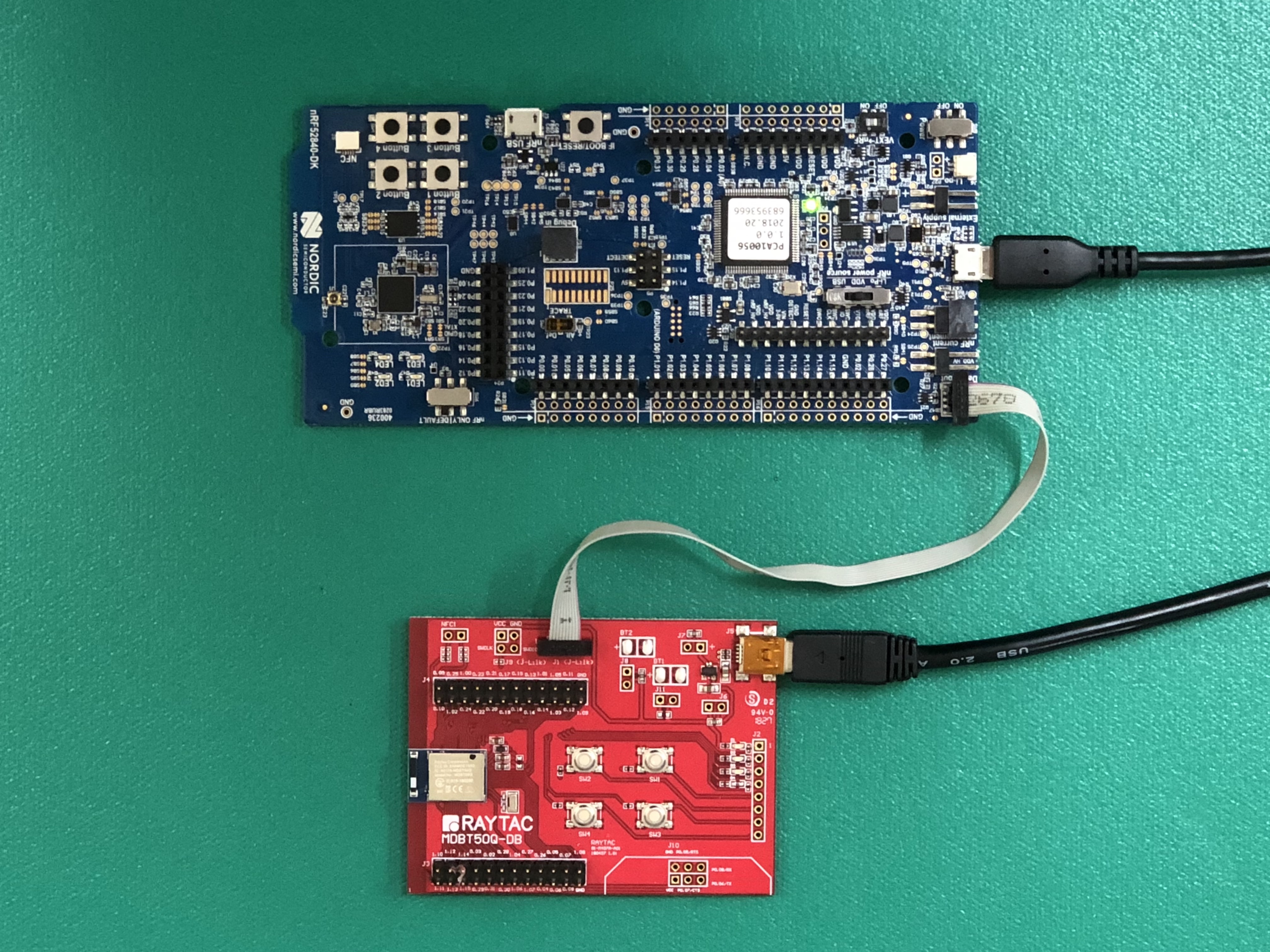
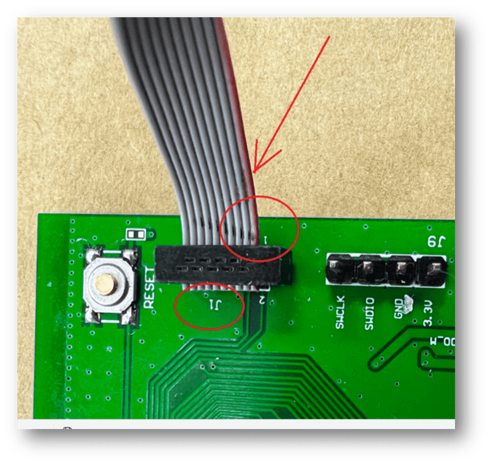
Step 1: Connect the J-Link on the Nordic DK with the AN54LV-DB-15 using the IDC ribbon cable.

Make sure to match the red side of the IDC ribbon cable with “1″ printed on the AN54LV-DB-15’s J-Link socket.


Step 2: Use the Type-C USB cables to supply power to both the nRF54L15-DK and the AN54LV-DB-15.

The outcome should be same as the picture above.

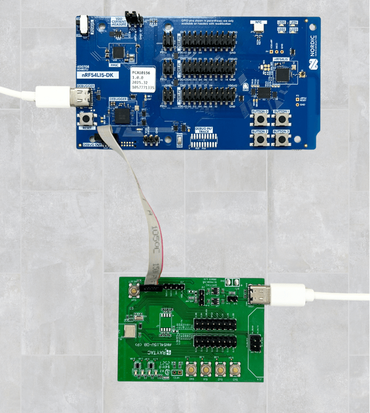
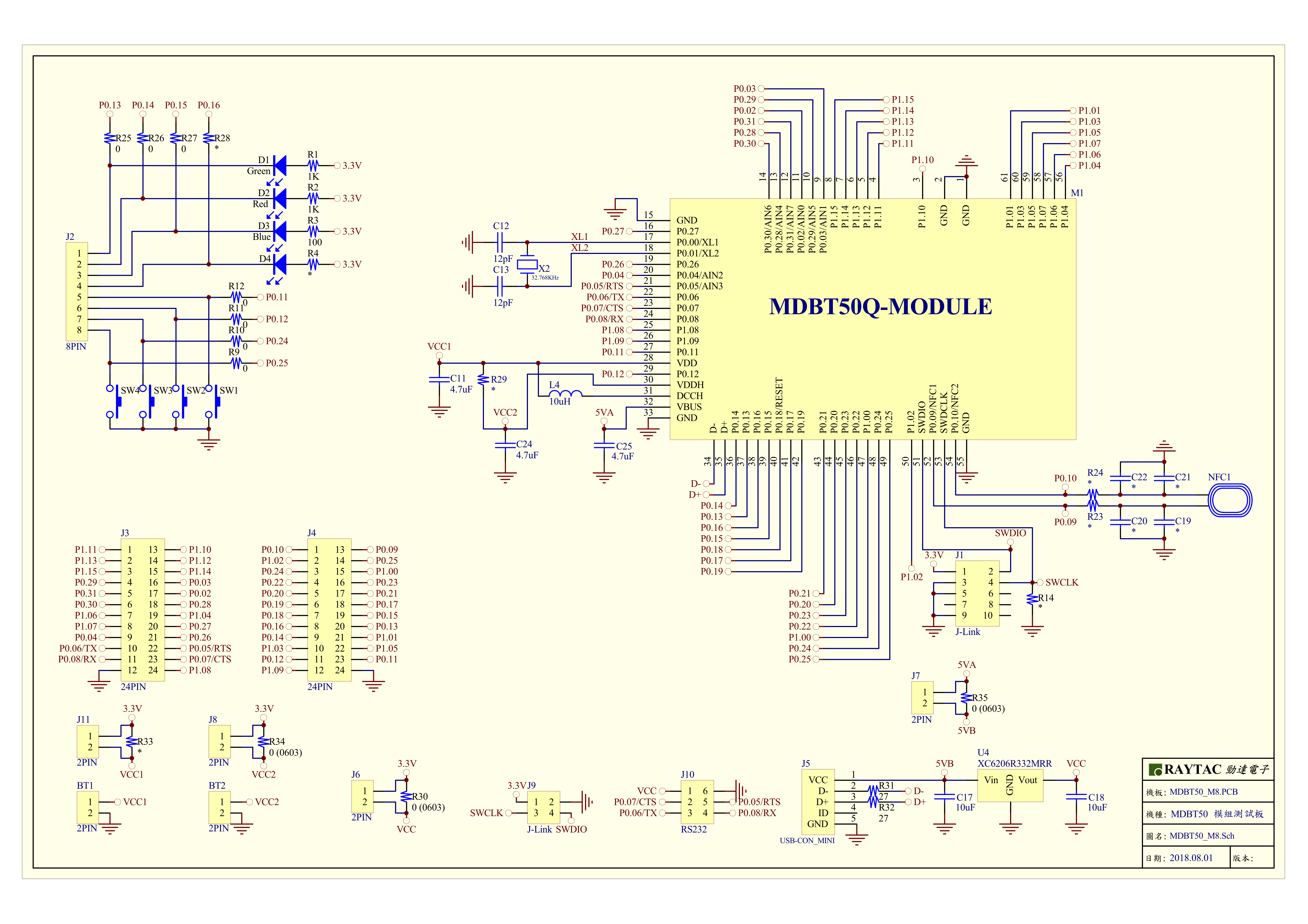
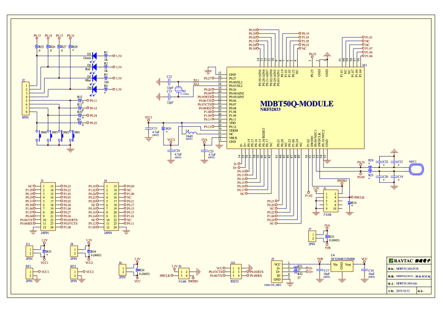
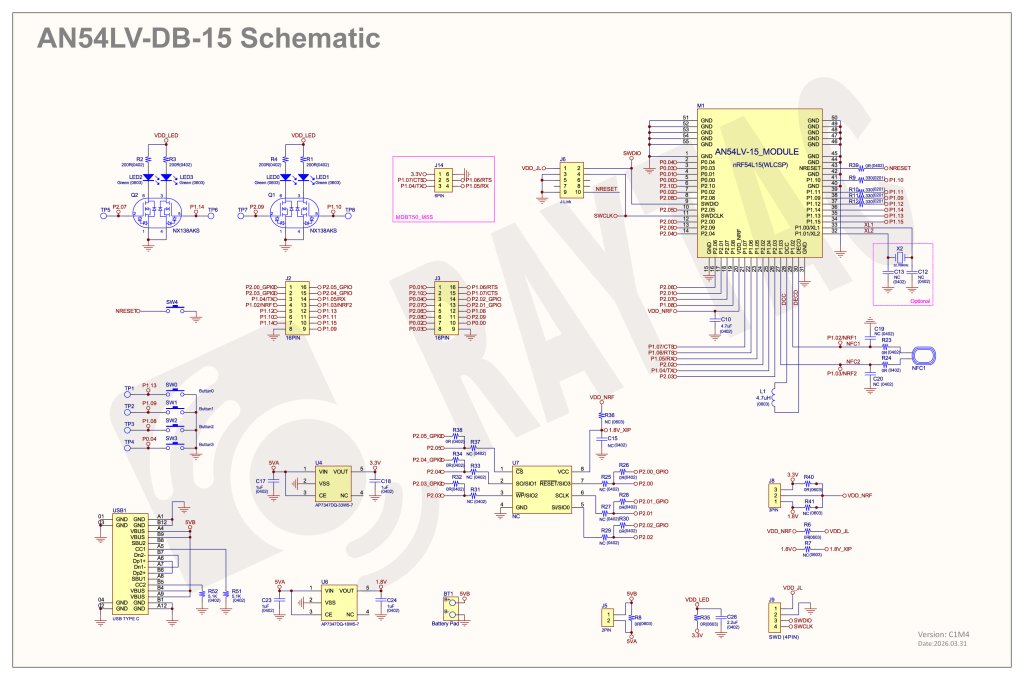
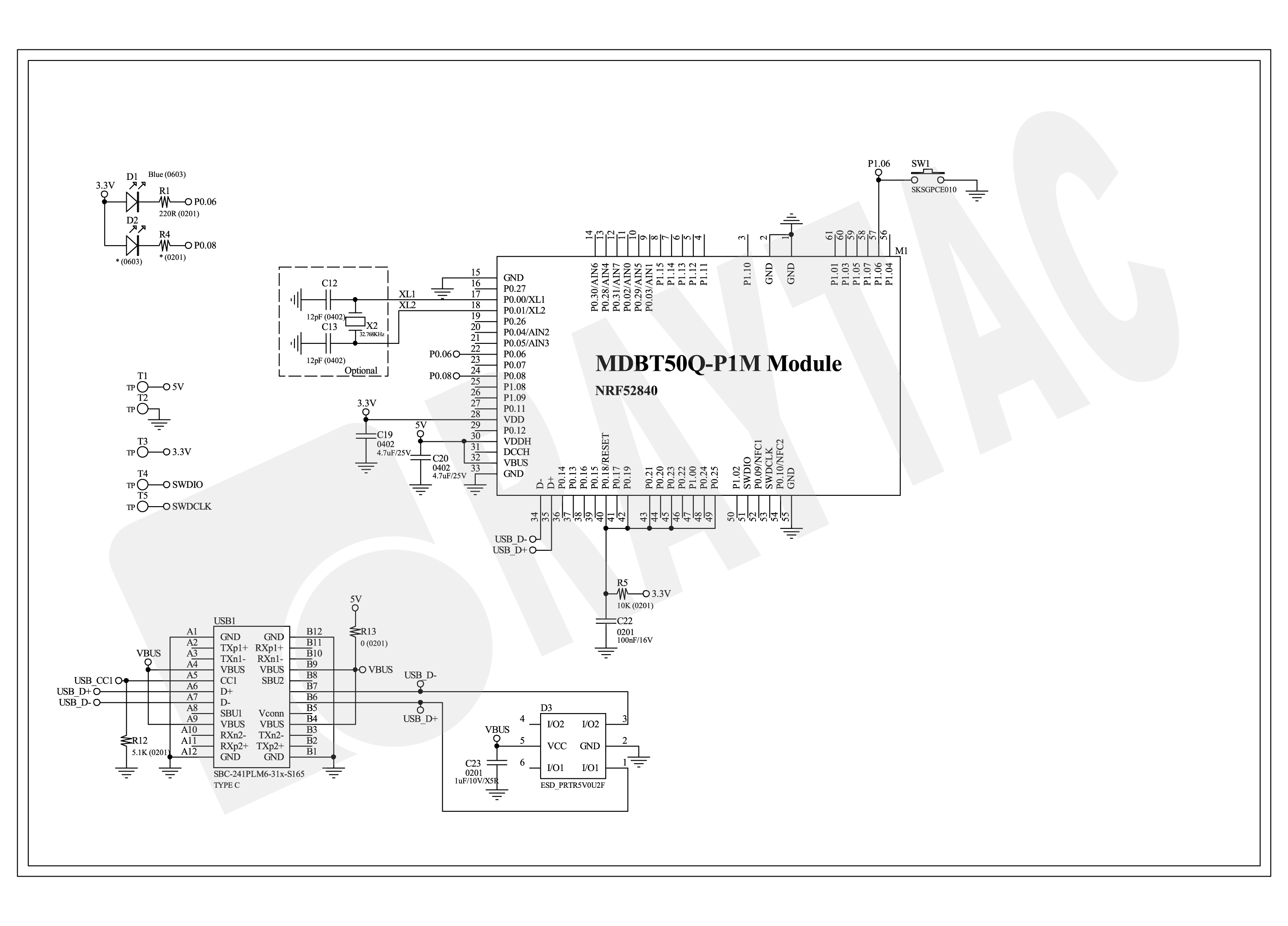
Step 3: AN54LV-DB-15 Schematic(Click on the schematic to zoom in):


2. Software Development Kit Resources and Environment Setup
Software Tool kits & Download Links:
Download nRF Connect for Desktop: Download nRF Connect For Desktop (Please Click Me)
Download nRF Command Line Tools: Download nRF Command Line Tools (Please Click Me)
Download Visual Studio Code(VS Code): Download nRF Command Line Tools (Please Click Me)

Setup Steps:
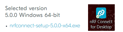
Step 1: Download the latest version of nRF Connect for Desktop. Choose the Windows 64-bit – version 5.3.1 installer (nrfconnect-setup-5.3.1-x64.exe). Once finished, you will see " nRF Connect for Desktop" on your PC.


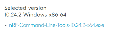
Step 2: Download the latest version of nRF Command Line Tools. Choose the Windows X86 64 – version 10.24.2 installer (nrf-command-line-tools-10.24.2-x64.exe)

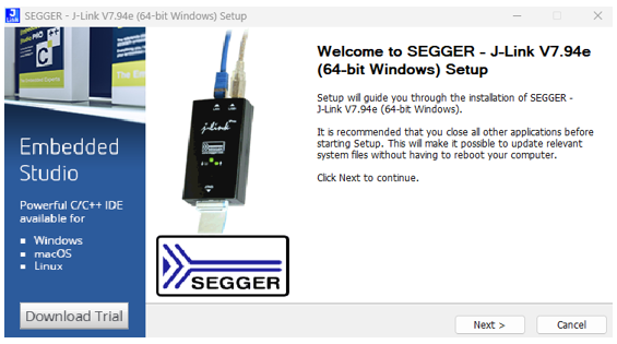
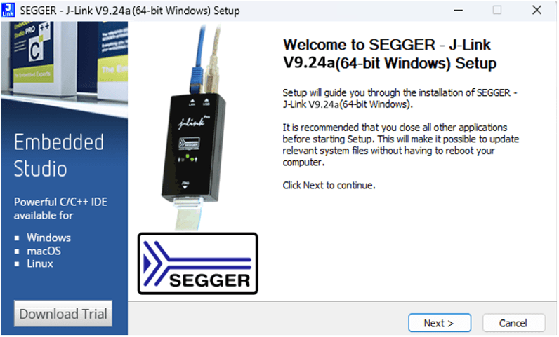
* Reminder: During the installation of the above two programs, a window may pop up prompting that SEGGER J-LINK needs to be installed or updated concurrently.

If you’re initiating Segger Embedded Studio (SES) application, please check the guideline here(Click me)


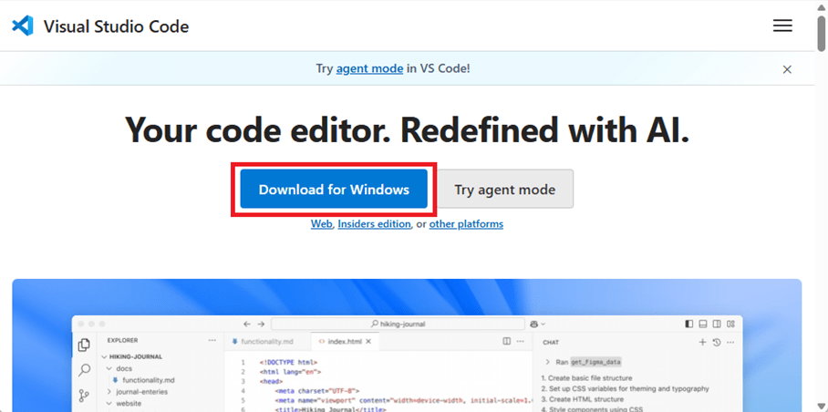
Step 3: Download the latest version of Visual Studio Code (VS Code). Choose Windows VSCodeUserSetup-x64 version 1.122 (VSCodeUserSetup-x64-1.122.1.exe). Once complete, you will see “Visual Studio Code" on your PC.

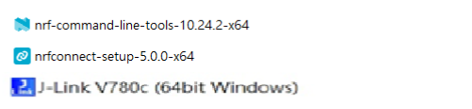
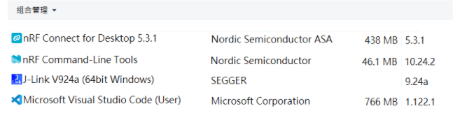
Step 4: After installation is complete, you can verify the installed packages in your PC’s Control Panel under “Programs and Features":


3. Software/Firmware Application Development
You can develop application programs within the VS Code IDE development environment.
Below steps are how to install and select your target SDK version (nRF Connect SDK v3.3.0 in this article):

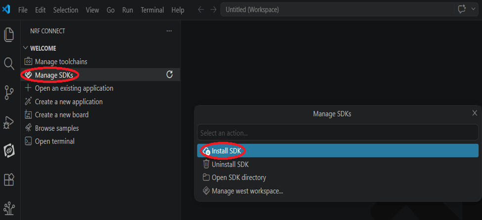
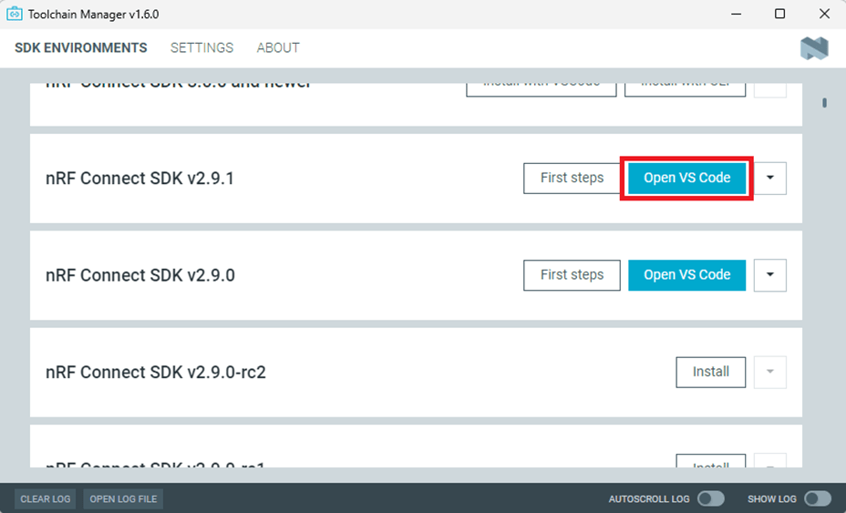
Step 1: Launch “VS Code"-> Select “nRF Connect" icon/extension on the side menu.


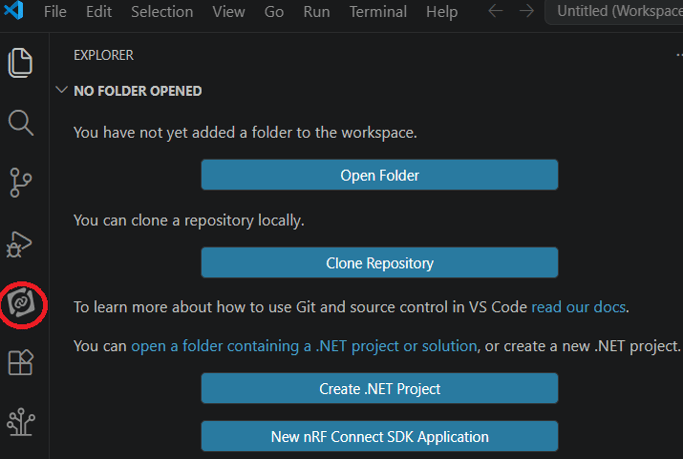
Click “Manage SDKs" and then select “Install SDK".


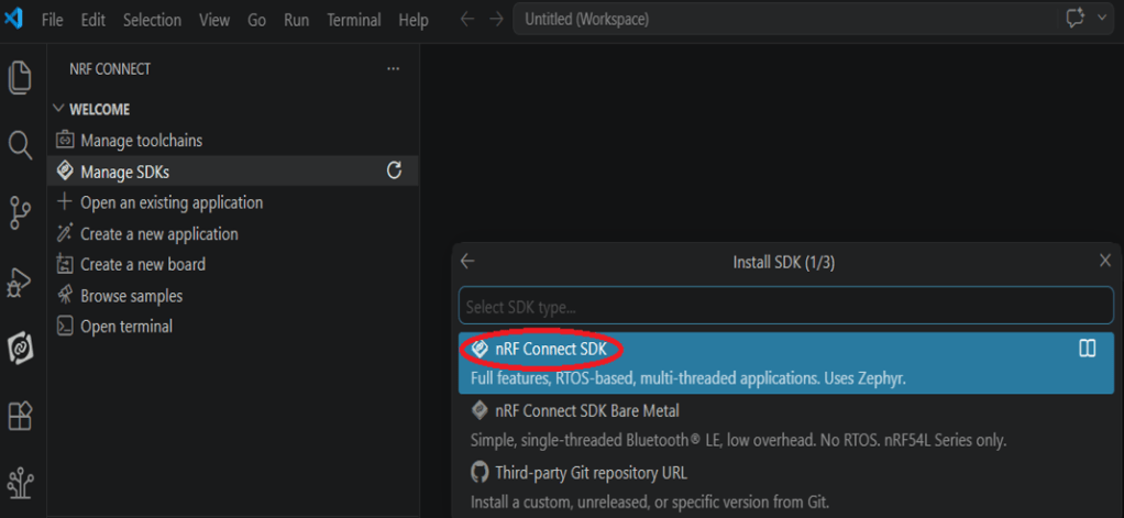
Step 2: Select “nRF Connect SDK".


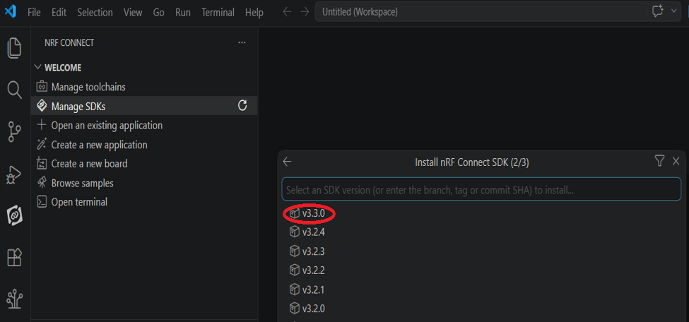
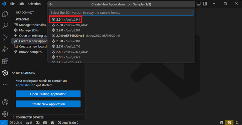
Step 3: You will see several available versions of nRF Connect SDK vx.x.x. It is highly recommended to choose and install NCS v3.3.0 or later. In this guide, we select nRF Connect SDK(NCS) v3.3.0.


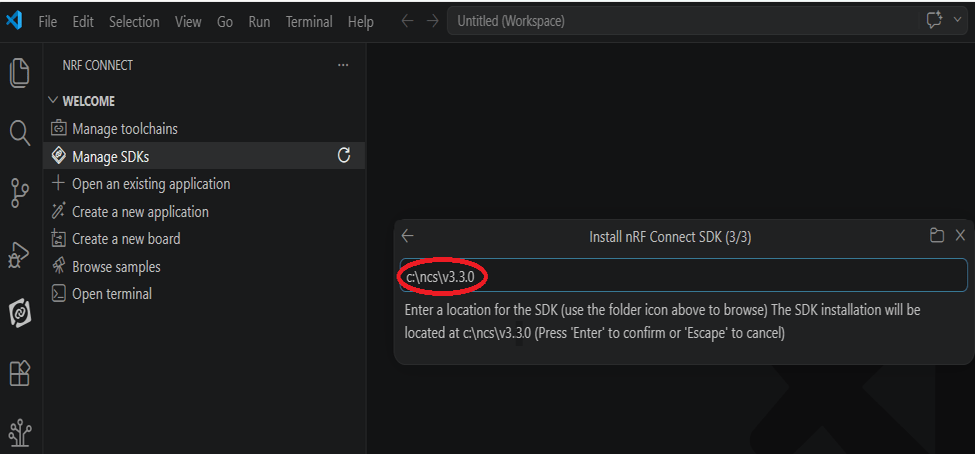
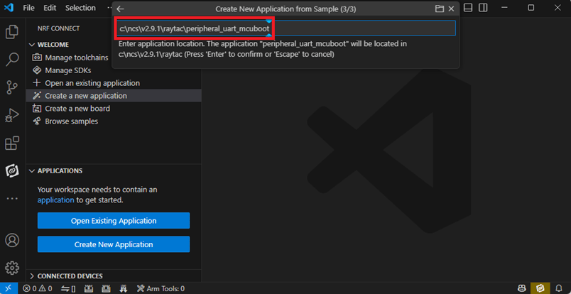
Step 4: Before starting the download for (NCS)v3.3.0, confirm your preferred target installation pathway.
By default, it is configured to c:\ncs\v3.3.0. Press ‘Enter’ to confirm.


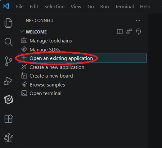
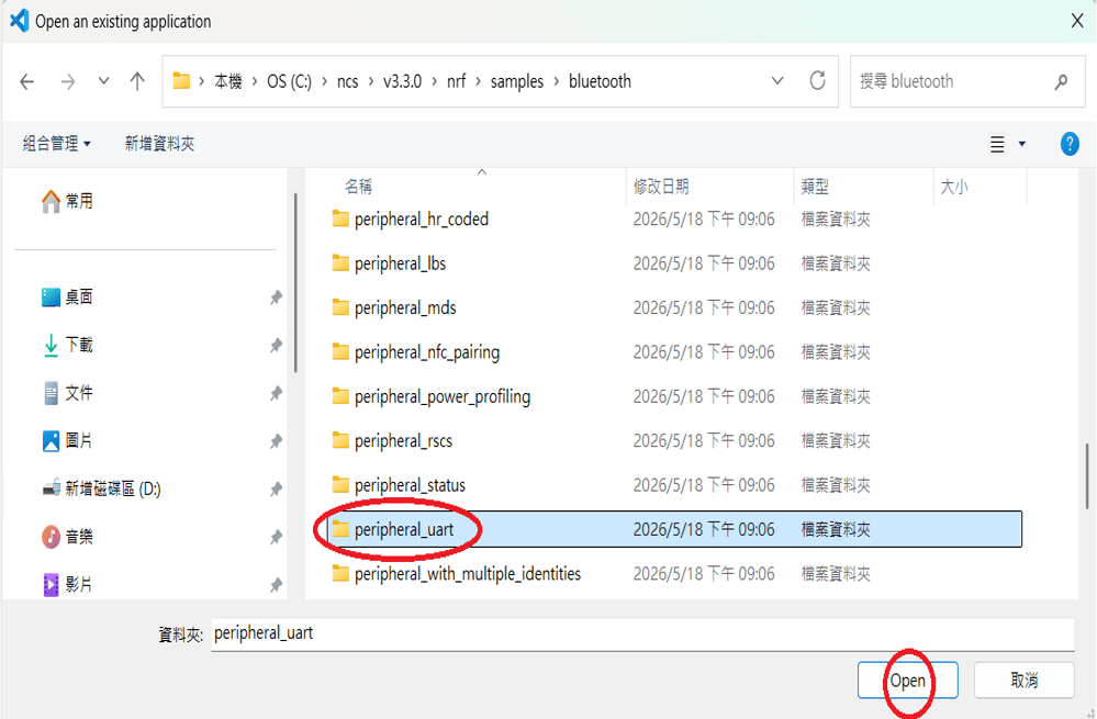
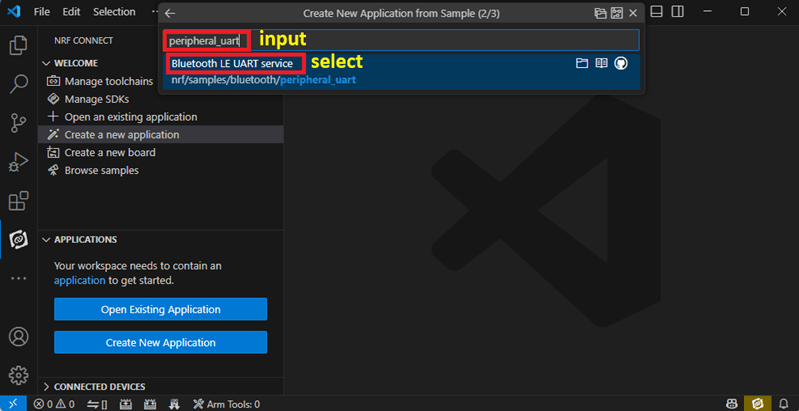
Step 5: Once the nRF Connect SDK v3.3.0 environment setup finishes successfully, open the Bluetooth sample folder and select the “peripheral_uart" application template, then click “Open".


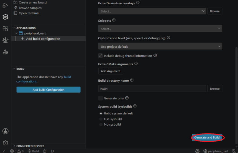
Step 6: In the “nRF Connect" layout, go to “Applications" –> “Add build configuration".


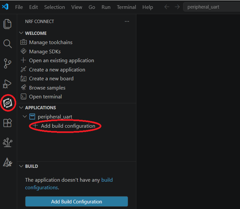
Under “Board target", look up and select “nrf54l15dk/nrf54l15/cpuapp" –> “Generate and Build".


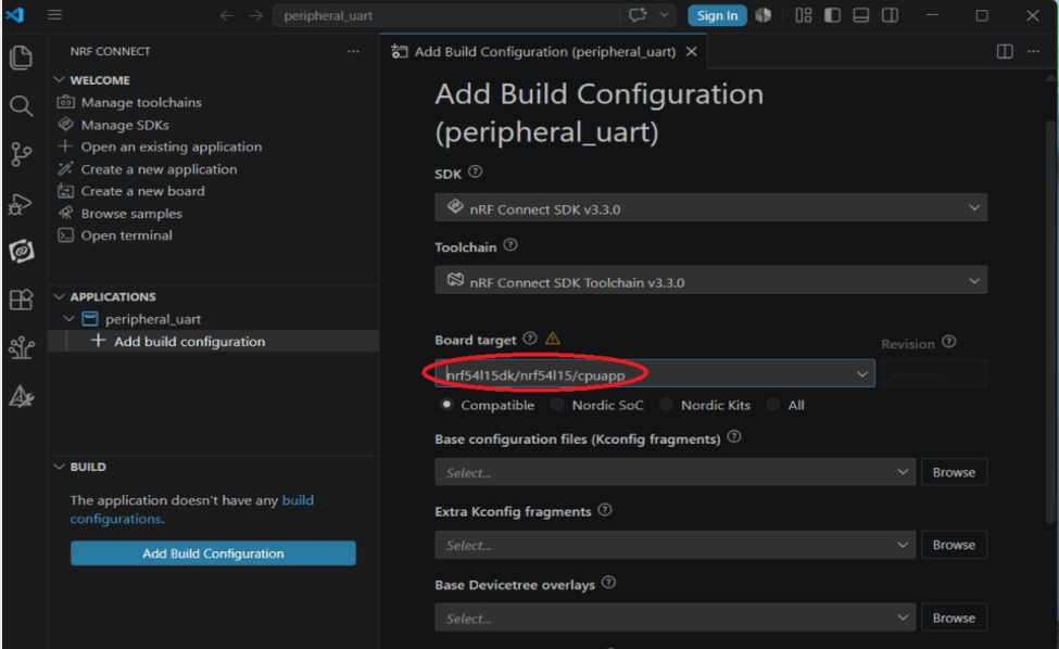
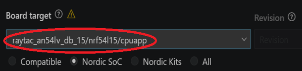
* Note: You can also choose the board name “raytac_an54lv_db_15/nrf54l15/cpuapp” for subsequent building and development.


After completing the configuration, you will see “Build complete".


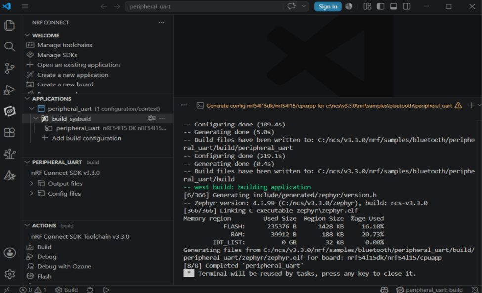
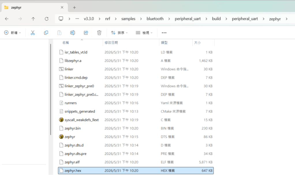
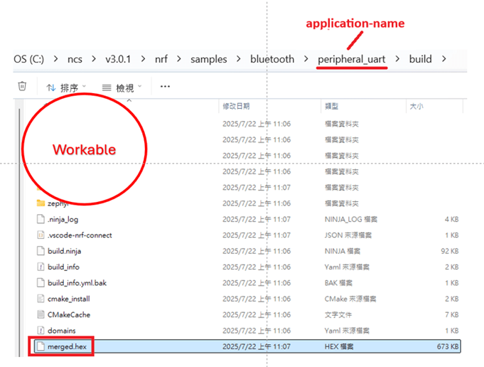
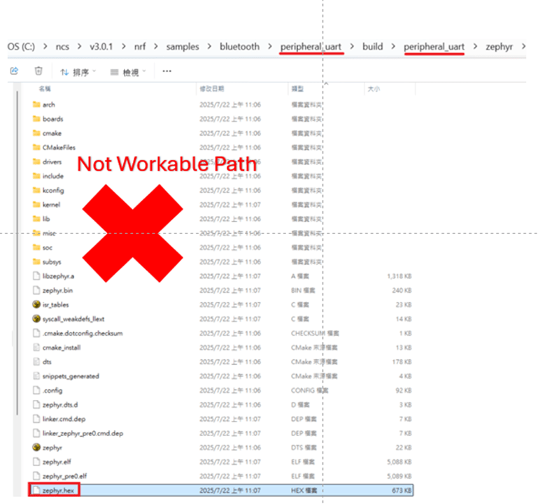
Step 7: Compilation completed. Once completed, a binary file named “zephyr.hex" will be generated in your “build" directory.


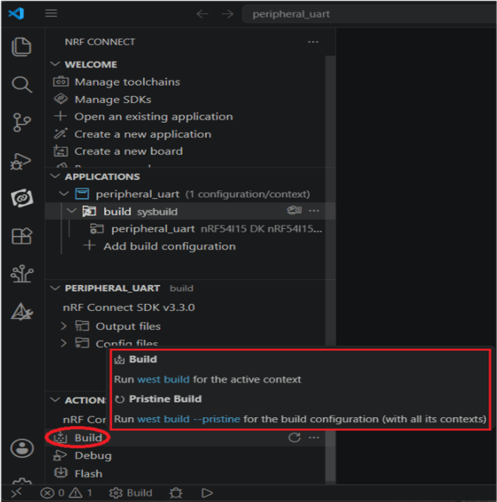
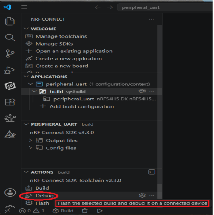
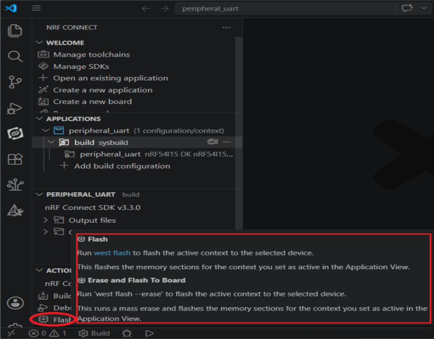
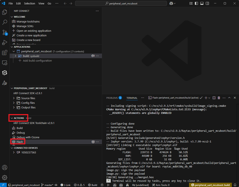
Step 8: Under the “ACTIONS" interface, you can switch between Build, Debug, and Flash functionalities dynamically.

Build


Debug


Flash


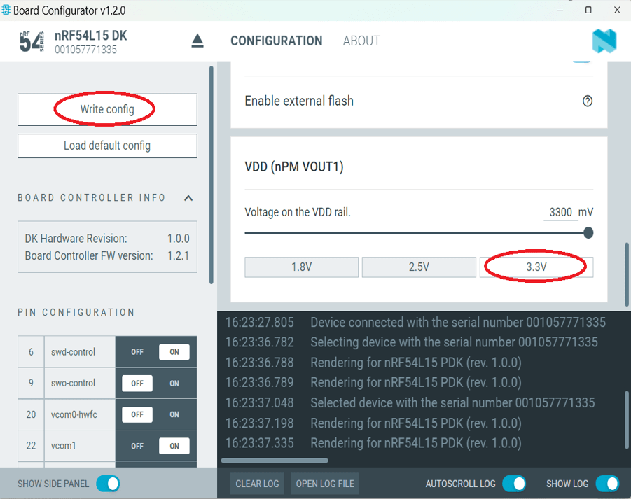
Step 9: CRITICAL BEFORE FLASHING/DEBUGGING: You have to change the VDD voltage configuration on the nRF54L15-DK board to 3.3V.
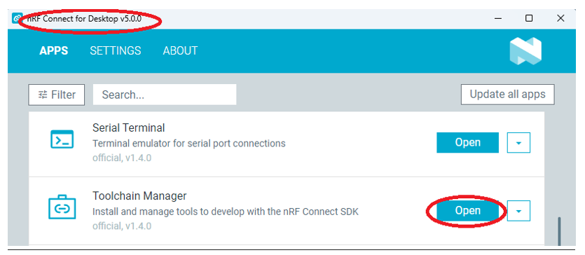
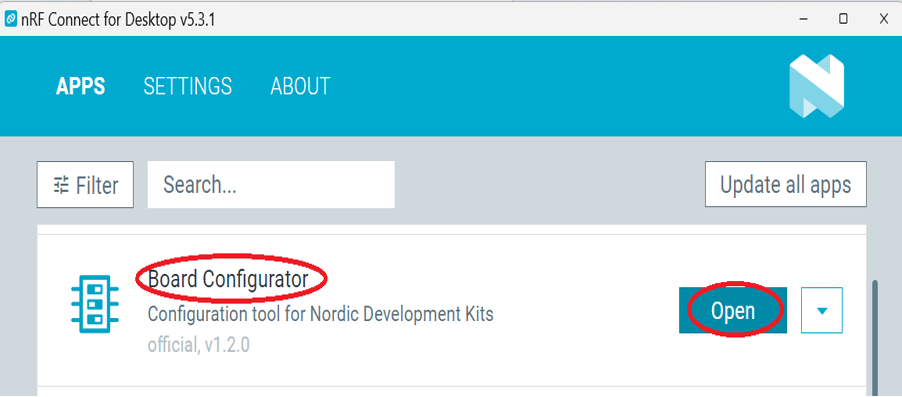
To do this: Launch “nRF Connect for Desktop" -> choose “Board Configurator" -> click “Open"


Change the VDD target selection value to “3.3V" -> click “Write config".


4. Flashing / Programming
The nRF Connect SDK (NCS) natively supports direct programming.
You can utilize the “Programmer" application tool to flash the compiled zephyr.hex binary file onto the target chip.
The exact procedure is detailed below:

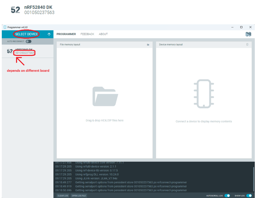
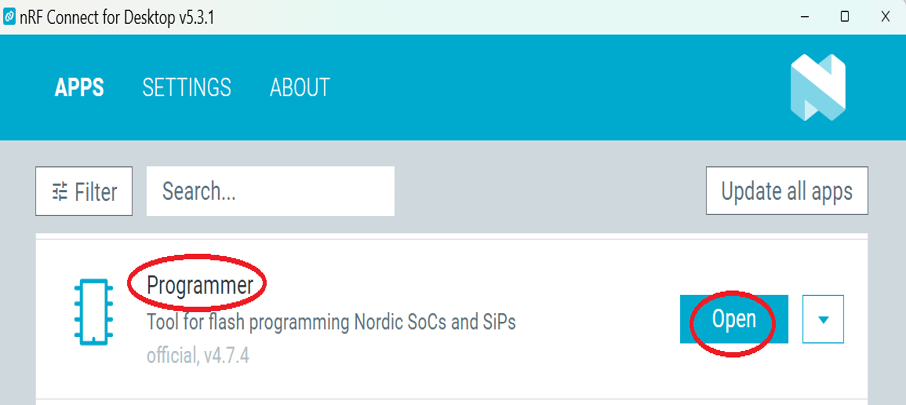
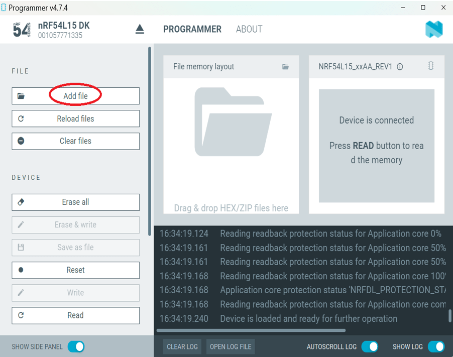
Step 1: Open “nRF Connect for Desktop" -> select “Programmer" and click “Open".


Click “Select Device" and choose “nRF54L15DK".
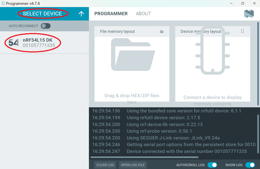
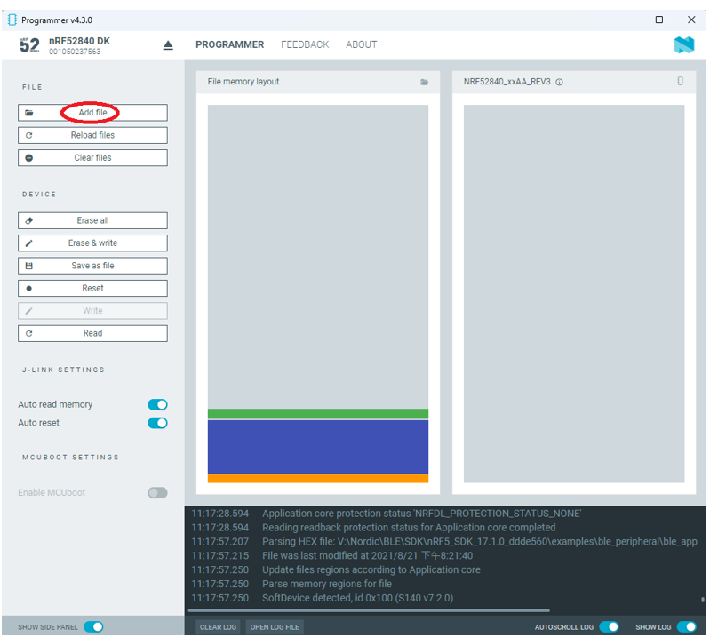
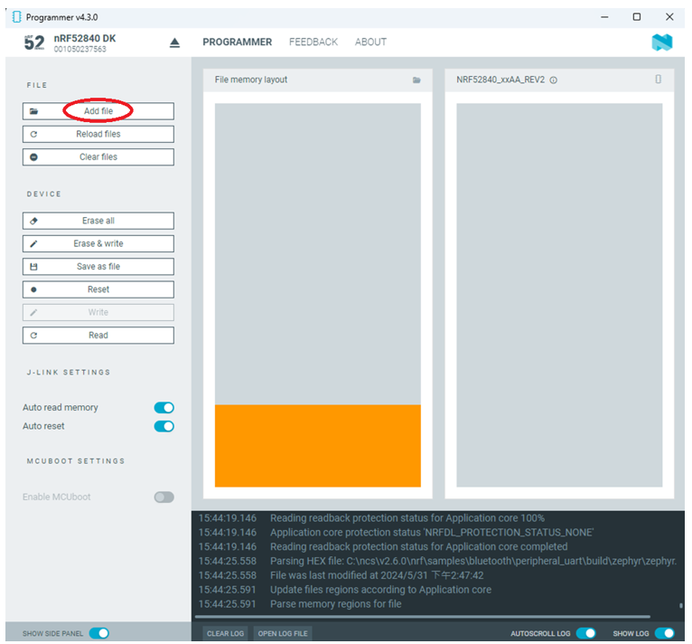

Click “Add file".


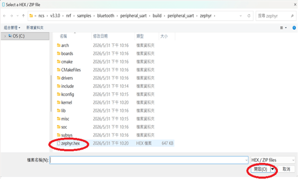
Step 2: Select your compiled target “.hex" file.


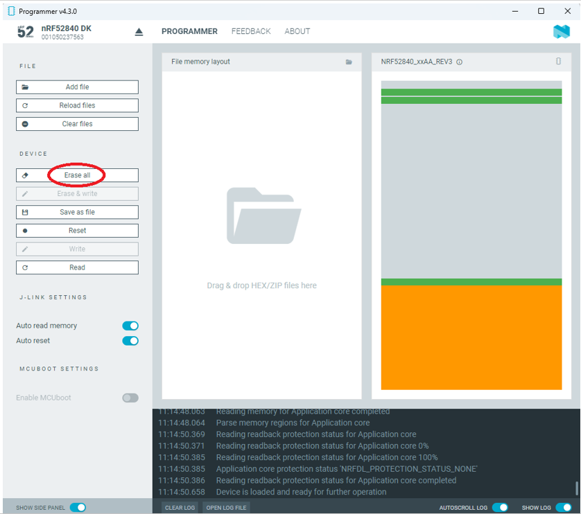
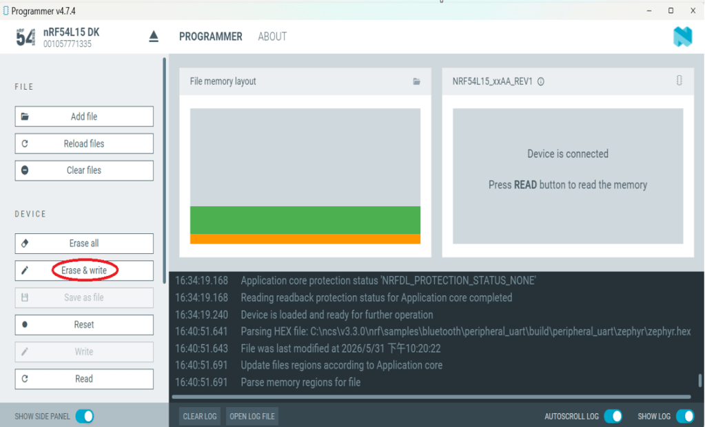
Click “Erase & write" to initiate the programming/flashing process.


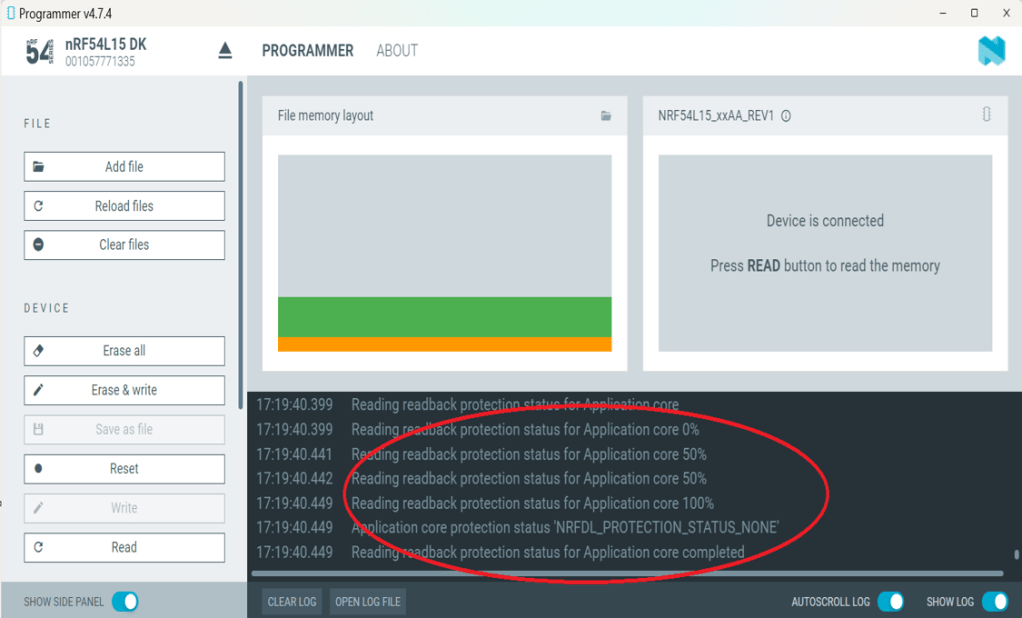
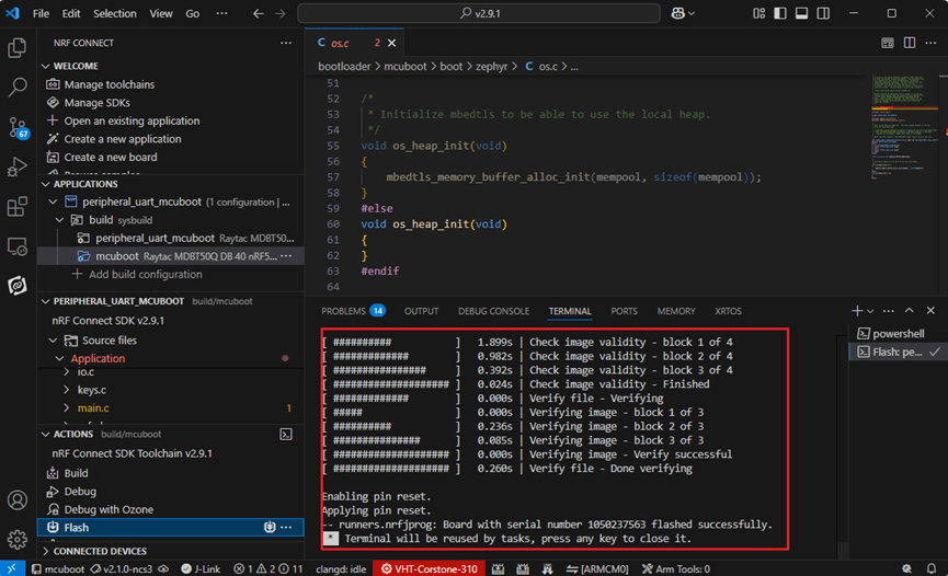
While flashing, a progress diagonal pattern will display on the right-hand panel.


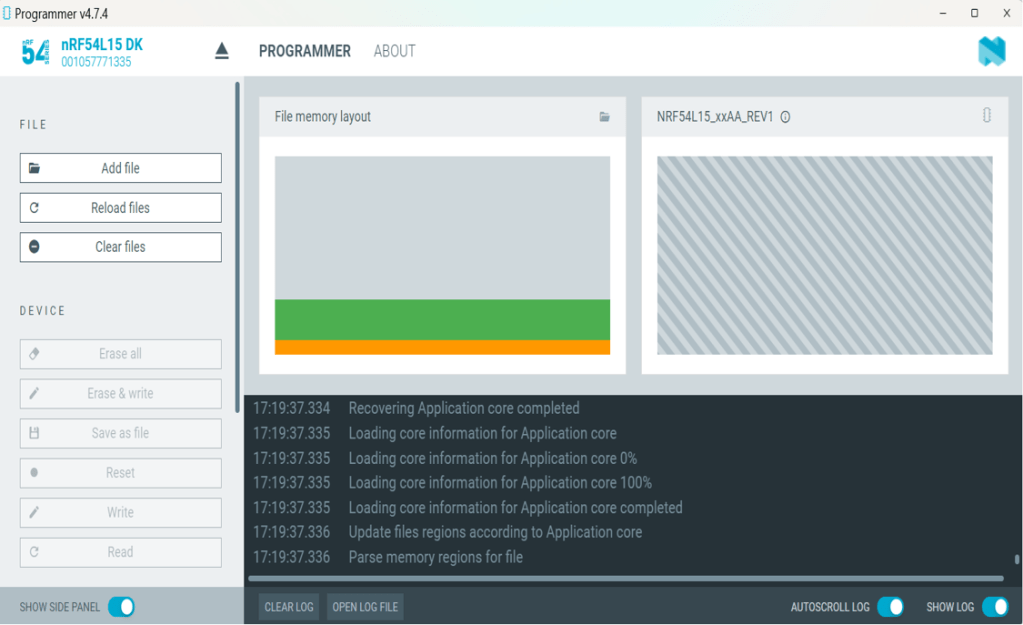
When the LOG shows a “completed" status text, it means that the programming/flashing is successfully done.


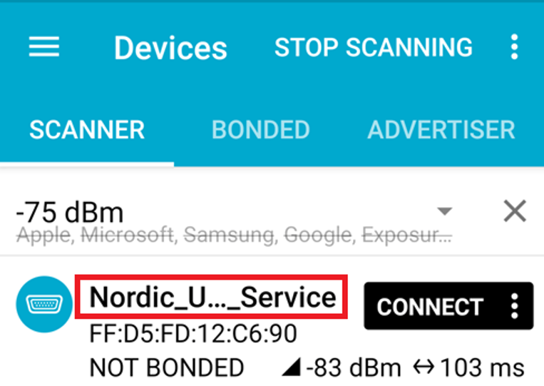
Step 3: After the flash operation completes, you can download the “nRF Connect for Mobile" app to scan and verify that the Raytac AN54LV-DB-15 development board is advertising normally.

“nRF Connect for Mobile" app download link: https://www.nordicsemi.com/Products/Development-tools/nRF-Connect-for-mobile


Useful References
nRF Connect SDK Documentation: https://developer.nordicsemi.com/nRF_Connect_SDK/doc/3.3.0/nrf/index.html

Nordic DevZone(technical support forum): Nordic Devzone for technical issue discussion


Edited by Account Manager: Christine Huang
Technical Guidance by R&D Manager: MW Lee

Raytac Corporation 勁達國際電子股份有限公司 / Raytac Corporation (USA) / abietec Inc.
A Bluetooth, Wi-Fi, and LoRa Module Maker/ODM & OEM Manufacturer based on
Nordic nRF54; nRF53: nRF52; nRF51; nRF7002
Infineon: CYW55912
NXP: RW610, RW612
Semtech: SX1262

Bluetooth Specification: BT6 ; BT5.4 ; BT5.3 ; BT5.2.
Wi-Fi Specification: Wi-Fi 6
LoRa Specification: LoRaWAN
Zephyr Project Silver Member

All products are FCC/IC/CE/Telec/KC/RCM/SRRC/NCC/WPC/RoHS/Reach Pre-Certified.

http://www.raytac.com
https://www.raytac.com/contact/
https://www.abietec.com/
email: sales@raytac.com
Tel: +886-2-3234-0208(TW)/+1-626-328-3827(USA)

Essential Tips for nRF54L15 HEX File Verification

Hi readers, did you know that Raytac offers a special service exclusively for our customers? 😉
We offer support services: HEX file verification and flashing firmware into modules per customer’s requests.
Compared to the series nRF52 and nRF53’s 2 in 1 or 3 in 1 merged hex files, nRF54L15 requires something slightly different. Following are the tips and suggestions.

Before building your own .hex file on Raytac’s nRF54L15 modules(Product link), please configure some settings(shown below) in advance.

In VS Code:

  1. Go to Add Build Configuration
  2. Find System Build (sysbuild) ➝ Choose Build System Default
  3. Click Generate and Build


Starting from NCS v2.8.0 (including later versions), the .hex file can be generated in two different paths.
1. ..\nrf\samples\bluetooth\application-name\build\merged.hex
2. ..\nrf\samples\bluetooth\application-name\build\application-name\zephyr\zephyr.hex


Using the AN54LQ/AN54LV series as an example:
When you provide the programming file (.hex) for production, please ensure that the file is taken from the following path:
1. ..\nrf\samples\bluetooth\application-name\build\merged.hex
And we also do not recommend renaming the merged HEX file due to Nordic suggestions.

For more details behind this suggestion, please refer to the Nordic DevZone link below.
https://devzone.nordicsemi.com/f/nordic-q-a/120313/how-to-modify-the-name-of-the-merged-hex-file


Suggested path:
1. ..\nrf\samples\bluetooth\application-name\build\merged.hex

Not recommended path:
2. ..\nrf\samples\bluetooth\application-name\build\application-name\zephyr\zephyr.hex
The zephyr.hex file is not recommended to be used for flashing or verification in the production process.

Thank you all for your patience in reading!
Best wishes for your projects – your success is Raytac’s success! 😊


For more information, please contact:
Raytac Contact Form: https://www.raytac.com/contact/
Raytac Sales email: sales@raytac.com
abietec Service email: service@abietec.com


Edited by Account Manager: Ms. Elfreda Guo


Raytac Corporation 勁達國際電子股份有限公司 / Raytac Corporation (USA) / abietec Inc.
A Bluetooth, Wi-Fi, and LoRa Module Maker/ODM & OEM Manufacturer based on
Nordic nRF54; nRF53: nRF52; nRF51; nRF7002
Semtech Specification: SX1262


Bluetooth Specification: BT6 ; BT5.4 ; BT5.3 ; BT5.2.
Wi-Fi Specification: Wi-Fi 6
LoRa Specification: LoRaWAN


All products are FCC/IC/CE/Telec/KC/RCM/SRRC/NCC/WPC/RoHS/Reach Pre-Certified.
http://www.raytac.com
https://www.raytac.com/contact/
email: sales@raytac.com
Tel: +886-2-3234-0208(TW)/+1-626-217-3139(USA)

MCUboot DFU Guide For Raytac MDBT50Q-DB-40 (Using NCS V2.9.1)

This guide teaches you how to use MCUboot for DFU (Device Firmware Update),
Combined with nRF Connect SDK (NCS) V2.9.1 to upgrade firmware on Raytac’s MDBT50Q series modules.


Table of contents:

  1. Hardware Set Up
  2. Software Kits resource download & install
  3. Compile and load the program
    a. Open VS Code
    b. Project setup
    c. Setup the situation for DFU over UART or DFU over USB
    d. Start compiling your project
    e. Load your compiled program into the MDBT50Q-DB-40 demo board
  4. DFU to MDBT50Q-DB-40 over UART / USB
  5. Execute USB DFU using AuTerm
  6. DFU using your custom keys

1. Hardware setup
– Equip Raytac’s MDBT50Q-DB-40 development board
– Ensure the board is connected via USB to your PC


2.Software Kits resources download & install
– Resources download:
nRF Connect for Desktop – Download nRF Connect for Desktop (Please Click Me)
nRF Command Line Tools – Download nRF Command Line Tools (Please Click Me)
Visual Studio Code – Download Visual Studio Code(Please Click Me)

Install nRF Connect for Desktop ➔ install Programmer and Toolchain Manager.


Open Toolchain Manager and install SDK V2.9.1.


Install Visual Studio Code


3. Compile and load the program
a. Open VS Code(Visual Studio Code)


Note:
If it’s your first time using the software: after installing all the extensions, you should see the same on your screen.


b. Project setup
b.1 Create an example code(In this article: peripheral_uart)
Please refer to the following steps:
Create a new application ➔ Copy a sample ➔ NCS V2.9.1


b.2 Name the Project: peripheral_uart
Input peripheral_uart and the corresponding example program will appear in the options section below.


Note: We named the project peripheral_uart_mcuboot to distinguish it.
This project will create a directory named peripheral_uart_mcuboot.

c. Build an environment for DFU over UART or DFU over USB
– Create a new application ➔ Open

Right click on the project name you just created (peripheral_uart_mcuboot), a pop-up menu will appear. Select the first option “Show in Explorer" from the pop-up menu to display all project files.


Then select New File to create a sysbuild.conf file.


select sysbuild.conf, left-click on it, and a blank box will show.


Input the file name and write: SB_CONFIG_BOOTLOADER_MCUBOOT=y


Parameters and instructions
Add a new file mcuboot.conf, in the sysbuild folder, and input the following parameters into the file. (Add relevant parameters according to UART or USB)
(Note: Please be informed if you want to use DFU over UART in the end, you should use UART when you first create the environment. Similarly, if you want to use DFU over USB, you should create the USB environment at the beginning.)

For DFU over UART
# Enable logging for MCUboot
CONFIG_LOG=y
CONFIG_MCUBOOT_LOG_LEVEL_WRN=y
# Enable Serial Recovery over UART
CONFIG_MCUBOOT_SERIAL=y
# Disable UART, since Serial Recovery uses it
CONFIG_UART_CONSOLE=n
# Configure the bootloader to use two slots
CONFIG_SINGLE_APPLICATION_SLOT=n
# Turn on a LED so we can see when Serial Recovery mode is active
CONFIG_MCUBOOT_INDICATION_LED=y


For DFU over USB
# Enable logging for MCUboot
CONFIG_LOG=y
CONFIG_MCUBOOT_LOG_LEVEL_WRN=y
# Enable Serial Recovery over UART
CONFIG_MCUBOOT_SERIAL=y
# Disable UART, since Serial Recovery uses it
CONFIG_UART_CONSOLE=n
# Configure bootloader to use two slots
CONFIG_SINGLE_APPLICATION_SLOT=n
# Turn on a LED so we can see when Serial Recovery mode is active
CONFIG_MCUBOOT_INDICATION_LED=y
# Configure serial recovery to use CDC_ACM, which by default uses the USB
CONFIG_BOOT_SERIAL_CDC_ACM=y
# Increase flash space for the MCUboot image to fit USB drivers
CONFIG_PM_PARTITION_SIZE_MCUBOOT=0x10000


Create a new file: mcuboot.overlay and add the following parameters.


For DFU over UART
/* Configure button and LED for Serial Recovery */
/ {
    aliases {
          mcuboot-button0 = &button0;
          mcuboot-led0 = &led0;
    };
  };


For DFU over USB
/* Configure button and LED for Serial Recovery */
/ {
    aliases {
          mcuboot-button0 = &button0;
          mcuboot-led0 = &led0;
    };
  };
/* Configure CDC ACM */
&zephyr_udc0 {
            cdc_acm_uart0: cdc_acm_uart0 {
                        compatible = “zephyr,cdc-acm-uart";
            };
};


Note: if you use DFU over USB, please enable the USB subsystem in prj.conf.


After all the setup is completed, you can start compiling your project.


d. Start compiling your project
Add Build Configuration ➔ Select target board ➔ In this example, choose raytac_mdbt50q_db_40/nrf52840.


Start compiling by clicking “Generate and Build" at the bottom-right corner.


e. Load your compiled program into the MDBT50Q-DB-40 demo board
After compiling without error, select the flash function to load your program into the MDBT50Q-DB-40 demo board.


If the below is shown, it means that you have successfully loaded your program into the demo board.


4. DFU to MDBT50Q-DB-40 through UART / USB
DFU over UART
Hold the SW2 button then plug the power into the USB connector.
The system will enter the bootloader mode.
You can then DFU the new firmware via the UART.


DFU over USB
If you update your firmware through USB, please also hold the SW2 button and connect the USB cable.


5. Execute USB DFU using AuTerm
AuTerm is a free-for-download PC software on Windows.
It allows you to update your new firmware on the MDBT50Q-DB-40 demo board.
Download link:
https://github.com/thedjnK/AuTerm/releases/download/v0.35a-pre/AuTerm_test_Win_x64_v0.35a.7z

Steps:
Select the tab Config to set the correct COM port.


Follow the sequences in the below screenshot.


You can use the file peripheral_uart_mcuboot.signed.bin for testing.
It is located in peripheral_uart_mcuboot/build.
Then follow the sequences in the below screenshot.
DFU will be completed when the progress reaches 100%.


6. DFU using your custom keys
When you compile the code, you will see the below warning.
Reason: It’s required to have your own private key to ensure your product’s security.
Following are the steps to enable security features.


Step 1. Create the key
First, install the imgtool program using pip.


Then use the following command to generate your private key in your project folder.
After the private key is generated, you can access it in your directory.


Step 2. Configure the project to use this key in sysbuild.conf

# Add MCUboot
SB_CONFIG_BOOTLOADER_MCUBOOT=y
#Add private key for MCUboot
SB_CONFIG_BOOT_SIGNATURE_KEY_FILE="\${APP_DIR}/private_key.pem"
# Configure key type
SB_CONFIG_BOOT_SIGNATURE_TYPE_ECDSA_P256=y


Step 3. Build and flash the project again. Your firmware will have security features.


Edited by Account Manager: Mr. Welson Kuo


Raytac Corporation 勁達國際電子股份有限公司 / Raytac Corporation (USA)
A Bluetooth, Wi-Fi, and LoRa Module Maker/ODM & OEM Manufacturer based on
Nordic nRF54; nRF53: nRF52; nRF51; nRF7002
Semtech Specification: SX1262


Bluetooth Specification: BT6.1 ; BT6 ; BT5.4 ; BT5.3 ; BT5.2.
Wi-Fi Specification: Wi-Fi 6
LoRa Specification: LoRaWAN


All products are FCC/IC/CE/Telec/KC/RCM/SRRC/NCC/WPC Pre-Certified.
http://www.raytac.com
https://www.raytac.com/contact/
email: sales@raytac.com
Tel: +886-2-3234-0208(TW)/+1-626-217-3139(USA)


Transition tips for program from MDBT50Q-RX (USB-A) to MDBT50Q-CX (USB-C)  with current NRF52840 project

Intro:

This is a guidance provided for those who is going to transit (or replicate) their project from Raytac MDBT50Q-RX (USB-A Dongle) to MDBT50Q-CX(USB-C Dongle).  In addition to the hardware spec change (Compact Size , LED, Button, Pin definition change) , the key firmware configuration should be made with changes to fit new USB-C Dongle MDBT50Q-CX.


RX-1                    CX-1

    MDBT50Q-RX                           MDBT50Q-CX


 Table of Contents:

1. Comparison chart: MDBT50Q-RX(USB-A) & MDBT50Q-CX(USB-C)

2. Firmware configuration

3. Create a merged hex file (2 in 1 or 4 in 1)

4. Firmware flashing process


1. Comparison chart: MDBT50Q-RX & MDBT50Q-CX

Comparison chart


2. Firmware configuration : MDBT50Q-RX → MDBT50Q-CX

Edit your current MDBT50Q-RX firmware with configuration change to align the PIN change to accommodate the hardware change.

Option 1. Using nRF5 SDK:

Make the definition set up of LED, BUTTON pin in the highlighted 4 sections.

Firmware configuration-nRF5


Option 2. Using NCS V2.6.X:

Use the board name: nrf52840dongle_nrf52840 and add the overlay file:

nrf52840dongle_nrf52840.overlay to the program (Devicetree Overlays),

then configure the below code definition into the overlay file:

/ {
   leds {
             compatible = “gpio-leds";
             led0_green: led_0 {
                      gpios = <&gpio0 6 GPIO_ACTIVE_LOW>;
                      label = “Green LED 0″;
             };
             led1_red: led_1 {
                     gpios = <&gpio0 8 GPIO_ACTIVE_LOW>;
                     label = “Red LED 1″;
             };
};

  buttons {
  compatible = “gpio-keys";
  button0: button_0 {
                  gpios = <&gpio1 6(GPIO_PULL_UP | GPIO_ACTIVE_LOW)>;
                  label = “Push button switch 0″;
                                   };
};
};

Firmware configuration-NCS


3. Create a merged hex file (2-in-1 or 4-in-1 hex file)


3A. Bootloader public key product

nrfutil keys generate public_key.pem → for zipping new firmware

nrfutil keys display –key pk –format code public_key.pem –out_file public_key.c

→ include public key to compile bootloader hex file

3A-1

3A-2


3B. Examples Demo

nRF5 SDK: nRF5_SDK_17.1.0_ddde560\examples\ble_peripheral\ble_app_uart\pca10056\s140

NCS V2.6.X: ncs\v2.6.0\nrf\samples\bluetooth\peripheral_uart


3C. How to generate bootloader setting file (if you need bootloader):

nrfutil.exe settings generate –family NRF52840 –application nrf52840_xxaa.hex –application-version 255 –bootloader-version 2 –bl-settings-version 1 bootloader_settings.hex


3D. Merge and create a 2-in-1 or 4-in-1 hex file

a). Merge 2-in-1 (no Bootloader file required):

mergehex.exe -m s140_nrf52_7.2.0_softdevice.hex nrf52840_xxaa.hex -o merge.hex

3D-a


b). Merge 4-in-1 (with Bootloader file & Bootloader settings file required):

mergehex.exe -m bootloader.hex bootloader_settings.hex  s140_nrf52_7.2.0_softdevice.hex nrf52840_xxaa.hex -o merge.hex

3D-b


4. Firmware flashing process

MDBT50Q-RX(USB-A):Manual wiring is required to have the firmware uploaded.

Please refer to the article: Firmware Coding & DFU onto MDBT50Q-RX

MDBT50Q-CX(USB-C):Built-in open bootloader included for simple DFU process..

Please refer to the article: User Manual of MDBT50Q-CX (nRF52840/nRF52833-based USB-C Dongle)


Edited by Sales Manager:
 Ms. Jocelyn Tsai
Technical guidance provided by Firmware Deputy Manager: Mr. Stanley Huang

Raytac Corporation 勁達國際電子股份有限公司
Bluetooth & WiFi & LoRa module maker based on Nordic nRF54, nRF53, nRF52, nRF7002 solution
BT5.4 &BT5.3 & BT5.2 & BT5.1 Qualified, FCC/IC/CE/Telec/KC/RCM/SRRC/NCC/WPC Pre-Certified.
Bluetooth Solution: nRF54, nRF5340, nRF52840, nRF52833, nRF52832, nRF52820, nRF52811, nRF52810, nRF52805, nRF51822
WiFi Solution: nRF7002
http://www.raytac.com
email: sales@raytac.com
Tel: +886-2-3234-0208

User Manual of MDBT50Q-CX (nRF52840/nRF52833-based USB-C Dongle)

MDBT50Q-CX is an advanced version of Raytac’s MDBT50Q-RX(USB-A Dongle).

MDBT50Q-CX has a more compact size, equips an up-to-date Type C USB Connector, and it has a built-in open bootloader for simple DFU process.

If you’ve been developing projects using MDBT50Q-RX in the past, you can find out in this manual how MDBT50Q-CX makes firmware compiling and loading much easier than before.

If you want to load firmware into MDBT50Q-CX, no wiring is needed. 

Simply plug the dongle into your device and USB DFU will be available.

MDBT50Q-CX (USB-C Dongle, nRF52840/nRF52833 solution): Product link

Size: 15.10 x32.85mm (0.59×1.29inches)


Table of Contents

A. Hardware intro

B. Software development environment setup

C. Firmware Implementation with NCS (nRF Connect SDK) or NRF5 SDK

D. Execute DFU (Device Firmware Update)


A. Hardware Intro

 <Pin Allocation>

2

< Schematic> (Click on the image to redirect to product page for Higher resolution photo)

Schematic Spec_MDBT50Q-CX_-240806


B.  Software development environment setup

Option 1. Compile in NCS(nRF Connect SDK)

(1) Install nRF Connect for Desktop:

B1

(2) Install Toolchain Manager and Programmer

B2

(3) Install nRF Connect SDK (NCS) → V2.6.0 is recommended.

B3

Option2. Compile in nRF5 SDK

(1) Download open source nRF5 SDK (Recommend: download the latest version:  17.1.0)

B4

(2) Install Segger Embedded Studio v5.42a (Recommended version)

https://www.segger.com/downloads/embedded-studio/

B5

※Welcome to contact Raytac sales team for v5.42a file of Segger Embedded Studio.


C. Implement firmware in NCS (nRF Connect SDK) or NRF5 SDK

We will use the two example codes below for this demo:

C1. NCS (nRF Connect SDK):

Example code path: \v2.6.0\nrf\samples\bluetooth\peripheral_uart

C2. nRF5 SDK:

Example code path: \nRF5_SDK_17.1.0_ddde560\examples\peripheral\usbd_ble_uart


C1. NCS (nRF Connect SDK): (Using nRF Connect SDK V2.6.0)

Step C1-1. Add build configuration to Board name: nrf52840dongle_nrf52840

C1

Step C1-2. Disable DCDC & DCDCHV by adding the below code into  prj.conf  file

CONFIG_BOARD_ENABLE_DCDC=n

CONFIG_BOARD_ENABLE_DCDC_HV=n

C2

Step C1-3. Fix the VDD power to 3.0V or 3.3V in board.c  file

The default power is 3.0V if you use board name: nrf52840dongle_nrf52840.

In this case, you don’t need to alter the power.

C3

Step C1-4. Click the rebuild icon to reconfigure the program.

C4

Step C1-5. The program will be saved automatically in the path below:

C:\ncs\v2.6.0\nrf\samples\bluetooth\peripheral_uart\build\zephyr\zephyr.hex


C2. nRF5 SDK:

Step C2-1. Open the program under:

\nRF5_SDK_17.1.0_ddde560\examples\peripheral\usbd_ble_uart\pca10056\s140\ses\ usbd_ble_uart_pca10056_s140.emProject

Step C2-2.  Fix the VDD power supply to 3.0V or 3.3V.

C2-1

Step C2-3. Start editing the project by opening the solution in Editor.

C2-2

Change the board name from PCA10056(nRF52840-DK) to PCA10059(nRF52840 dongle).

Save and re-compile the program after the amendment.

C2-3

Click the program file name and save the modified project.

C2-4

Press “Yes” to re-load the new set up value into configuration.

C2-5

The default code in sdk_config.h is: NRF_LOG_BACKEND_UART_ENABLED 1 (in red frame);

Please change 1 to 0 to make the LED light work.

Stanley修改內容_20240806

Press “Rebuild Solution” to make sure all the parameters you’ve modified are reconfigured.

C2-6

Step C2-4. The program will be saved automatically under the path below:

V:\nRF5_SDK_17.1.0_ddde560\examples\ble_peripheral\ble_app_uart\pca10056\s140\ses\Output\Release\Exe\ble_app_uart_pca10056_s140.hex


D. Execute DFU (Device Firmware Update)

Reminder: 

No extra bootloader can be programmed into MDBT50Q-CX until you manually wire the pins on the PCB and erase the built-in bootloader.  You can simply operate DFU using MDBT50Q-CX’s bootloader.

Step D1. How to enable DFU?

(1) Press the button on MDBT50Q-CX

(2) Plug MDBT50Q-CX into your device while pressing the button

(3) Press and wait for approx.1 second until the LED light turns on. → DFU is activated.

(4) Release the button

※When Bootloader mode is enabled, the LED light on MDBT50Q-CX will twinkle continuously. 

D1

Step D2. Open the built-in DFU Bootloader

nRF Connect Desktop →  Programmer  → SELECT DEVICE  → Open DFU Bootloader

D2

You have successfully entered bootloader mode after you see the screen as below.

D3

Step D3. Add ready firmware file into the Programmer

(The program completed and saved during Step C1-5(NCS) or Step C2-4(nRF5 SDK))

※If you’re using nRF5 SDK, you need to add the soft device file into your program for loading firmware.

※Soft device path:

nRF5_SDK_17.1.0_ddde560\components\softdevice\s140\hex\s140_nrf52_7.2.0_softdevice.hex

D4

Step D4. Load the firmware and write it into the MDBT50Q-CX

D5

Step D5. Process FW DFU

D6

Step D6.  DFU Completed. The appointed firmware is successfully loaded into MDBT50Q-CX.

D7

※Any failure during the DFU process will leave you under bootloader mode.

Last-failure

If this happens, simply restart the firmware writing process from Step D4 to reload your firmware into MDBT50Q-CX.


Edited by Sales Manager: Ms. Jocelyn Tsai
Technical guidance provided by Firmware Deputy Manager: Mr. Stanley Huang

Raytac Corporation 勁達國際電子股份有限公司
Bluetooth & WiFi & LoRa module maker based on Nordic nRF54, nRF53, nRF52, nRF7002 solution
BT5.4 &BT5.3 & BT5.2 & BT5.1 Qualified, FCC/IC/CE/Telec/KC/RCM/SRRC/NCC/WPC Pre-Certified.
Bluetooth Solution: nRF54, nRF5340, nRF52840, nRF52833, nRF52832, nRF52820, nRF52811, nRF52810, nRF52805, nRF51822
WiFi Solution: nRF7002
http://www.raytac.com
email: sales@raytac.com
Tel: +886-2-3234-0208


Firmware Coding & DFU onto MDBT50Q-RX

Hi there, 

Here introduce the firmware perspective about how to program your code onto MDBT50Q-RX dongle.

Believed all readers have done the hardware setting and now has well prepared to load the code onto the dongle. (If not yet done the hardware setting, pls find it here)

In this blog, we will introduce the procedure based on below 2 scenarios

  • First time to load the code
  • DFU Firmware update by USB or OTA (through Bluetooth over the air)

How to update nRF DeviceFamilyPack version to 8.27.1

From the article “Change to nRF52833 module? What the Hardware & Firmware Setting Need To Review?“, Raytac has highlighted Keil users need to update nRF Device Family Pack version to 8.27.1 for SDK16

Here introduced how to change the nRF DeviceFamilyPack version.

Modify nRF DeviceFamilyPack version to V8.27.1

Change to nRF52833 module? Introduce What the Hardware & Firmware Perspective Need To Review!

Developer who currently are using nRF52840 based modules must be excited waiting for nRF52833’s distribution. Most developers are aware that nRF52833 supports long range, multi protocol and USB interface but has less RAM and Flash memory rather than nRF52840 and no doubt is the best alternative to have cost effective without extra efforts.

Raytac has released 3 models of nRF52833 based modules just at the same time when Nordic released, MDBT50Q-512K / MDBT50Q-P512K / MDBT50Q-U512K. Both nRF52840 and nRF52833 module are based on same form factor and pin out. To have quick visual identification finding the difference, Raytac’s nRF52833 modules are built by Green PCB but nRF52840 modules are Blue.

Raytac BLE Module-nRF52840 &amp; nRF52833

How To Use nRF52840/nRF52833 module DevKit(MDBT50Q series) – 2024 Update – Applied to nRF5 SDK & nRF Connect SDK

Preface:
Here provides an easy introduction of How to set up of nRF52840 & nRF52833 Module Demo board MDBT50Q-DB-40 (for nRF52840) & MDBT50Q-DB-33 (for nRF52833)


MDBT50Q-DB-40  is a Demo Board built by Raytac’s MDBT50Q-1MV2  with Red PCBA deployed nRF52840 SoC with Bluetooth 5 & Thread Combo, with 1MB Flash Memory and 256KB RAM and Chip Antenna.
 
MDBT50Q-DB-33 is a Demo Board built by Raytac’s MDBT50Q-512K with Green PCBA deployed nRF52833 SoC with Bluetooth 5 & Thread Combo, with 512KB Flash Memory and 128KB RAM and Chip Antenna.
 
Both demo boards are Bluetooth BT5.4 qualified and FCC, IC, CE, Telec, KC, SRRC, RCM, NCC, WPC pre-certified.

Table of contents:

1.1 Hardware Set Up

1.2 Software Kits resources & preparations

1.3 Flash the ready firmware into Raytac’s module

1.4 DFU to MDBT50Q-DB-XX through USB interface 


1.1 Hardware Set Up
 
MDBT50Q-DB-XX package contains:
  • 1 x MDBT50Q-DB-40/MDBT50Q-DB-33
  • 1 x IDC Wire
  • 1 x Data/Power Mini USB Wire(for data transferring)

Where to buy MDBT50Q-DB-XX?

MDBT50Q-DB-40 (nRF52840 Solution)

MDBT50Q-DB-33 (nRF52833 Solution)
Connect Nordic NRF52-DK/NRF52840-DK Connect with MDBT50Q-DB-40 by IDC Wire

※Note: PCA10056 (NRF52840-DK) / PCA10040 (NRF52832-DK) / PCA10100(NRF52833-DK)

Power up MDBT50Q-DB-XX using Mini USB

IMG_0064.jpg
MDBT50Q-DB-40

MDBT50Q-DB-40 Schematic:

MDBT50Q Demo Board Schematic-V2.jpg

MDBT50Q-DB-33 Schematic:

MDBT50Q-DB-33 Schematic


1.2 Software kits resources & preparations

Resources:

Download nRF Connect For Desktop (Please Click Me)

Download nRF Command Line Tools (Please Click Me)

Download NRF5 SDK (The latest V17.1.0) (Please Click Me)

Download Visal Studio Code(Please Click Me)

Preparations:

Option 1.  NRF5 SDK (The latest version V17.1.0)

  1. 1.0_ddde560\components\softdevice\s140\hex\ s140_nrf52_7.2.0_softdevice.hex
  2. 1.0_ddde560\examples\ble_peripheral\ble_app_uart\pca10056\s140\arm5_no_packs\_build\ nrf52840_xxaa.hex

*Tips: If you go with nRF5 SDK option, please consider to add a bootloader hex file if you’re going to make DFU requests in the future.

Option 2.  NCS (Recommended version V2.6.0)

螢幕擷取畫面 2024-06-04 161138

2A.  Find “Toolchain Manager” in app nRFConnect for Desktop

螢幕擷取畫面 2024-06-04 161251

2B.  Install nRFConnect SDK V2.6.0 to your working site.

螢幕擷取畫面 2024-06-04 161333

2C. Prepared with the latest version of nRF Command Line Tools
螢幕擷取畫面 2024-06-04 161627
 
**Note: SEGGER J-LINK Upgrade message might pop up while you’re doing above download.
螢幕擷取畫面 2024-06-04 161724
 
2D. Locate all the necessary kits for programming in PC

螢幕擷取畫面 2024-06-04 161810


1.3 Flash the ready firmware into Raytac’s module

Intro:

With the ready built code of zephyr.hex (Made through NCS) or nrf52840_xxaa.hex & s140_nrf52_7.2.0_softdevice.hex (Made through nRF5-SDK) file for application, we would like to move onto  flashing code into the MDBT50Q BLE module(mounted on MDBT50Q-DB-XX demo board).

Step1.  

Execute nRF Connect >>  Programmer  > > Open

螢幕擷取畫面 2024-06-04 161858

Step2.

Click “SELECT DEVICE” >> Find icon “nRF52840 DK” which is detected by the programmer app

螢幕擷取畫面 2024-06-04 162005

Step3.

Click “nRF52840 DK”>> “Erase All” to remove flash memory inside MDBT50Q BLE Module

螢幕擷取畫面 2024-06-04 162106

Step4.

Click “Add File” to load application zephyr.hex into programmer

螢幕擷取畫面 2024-06-04 162202

✓ If you’re using nRF Connect SDK for code compiling as above, Program the hex file to MDBT50Q BLE module on the MDBT50Q-DB Demo board:

C:\ncs\v2.6.0\nrf\samples\bluetooth\peripheral_uart\build\zephyr\zephyr.hex

✓ If you’re using NRF5 SDK for code compiling, you need to program the following two hex files into the MDBT50Q BLE module on the demo board:

nRF5_SDK_17.1.0_ddde560\components\softdevice\s140\hex\s140_nrf52_7.2.0_softdevice.hex

nRF5_SDK_17.1.0_ddde560\examples\ble_peripheral\ble_app_uart\pca10056\s140\arm5_no_packs\_build\ nrf52840_xxaa.hex


!! Important Tips to securing DFU:!!

If it is confirmed to require DFU in this project, it is recommended to build a 4-in-1 bootloader.  (The 4-in-1 bootloader should be created by your own after having the private key activated uniquely).

(1) bootloader.hex

(2) bootloader_setting_file.hex

(3) s140_nrf52_7.2.0_softdevice.hex

(4) nrf52840_xxaa.hex

螢幕擷取畫面 2024-06-04 162300


1.4 DFU to MDBT50Q-DB-XX through USB interface

Intro : Before DFU implement , Please make sure the bootloader file has been installed in your MDBT50Q BLE module.

※Note: NRF52840 SoC supports USB interface to utilize Device Firmware Update (DFU).

How do I prepare the software??

  • Download nrfutil.exe file from Nordic website .
  • It is workable to do List, Program, Recover, Erase, and operations with nRFutil device command to Nordic device.
  • Open DOS mode to install device command type: nrfutil install device

(Jocelyn) How To Use NRF52840 NRF52833 module Dev Kit (MDBT50Q Series) 2024 version - Release file

How do I setup the hardware??

  1. Press Switch 4 and hold
  2. Power up Demo Board
  3. Blue LED Lights on
  4. Demo Board successfully enters into USB DFU Mode

螢幕擷取畫面 2024-06-04 162504

How do I prepare the firmware??

**USB DFU works only in DOS mode.

**USB DFU only works when USB Bootloader installed in current loaded firmware (inside BLE Module)

A single, merged 4-in-1 hex file is required, which includes:

Bootloader, Bootloader setting, Softdevice, and Application.

Firmware DFU requires a .zip file.

USB DFU Execution Steps:

Step 1. When Blue LED Lights on with MDBT50Q-DB (Ready to enter USB DFU Mode)

Step 2. Find out Com Port No. “nRF52 SDFU USB(COMxx)”

螢幕擷取畫面 2024-06-04 162542


Step 3. Execute USB DFU

Option 1. Using device program command:

(1) List the devices with a DFU trigger interface by running:

nrfutil device list –traits nordicDfu

Option1-1

(2) Program new firmware to a device identified by its serial number by running:

nrfutil device program –firmware .zip nrf52840_xxaa.zip –serial-number XXXXXXXXXXXX

Option1-2

Bluetooth Project: How to program your firmware to module

After setup been done, here comes the next question: How to program the firmware in to the module. We are using some simple instruction in below for reader’s quick reference.

Hardware

You will need a Nordic nRF5X DK or a Segger J-link as programmer to load the firmware. To use Nordic nRF5X DK to debug the SoC as well, you will need to order corresponding nRF5X DK to match the SoC number. For example, order nRF52840 DK to debug nRF52840 SoC or order nRF52 DK to debug nRF52832/52810 SoC. But if you are only using it as programmer, any version of nRF5X DK will work as we only use the J-link on this board.

Software

Please download Nordic nRFGo Studio for programming. Remember to install nRF5X Command Line Tools if the board was not detected by nRFGo Studio. Once they are all connected, you can then start programming. Please make sure to “erase all” every time before programming.

For more tutorials and demo of sample code, please visit Nordic’s DevZone and Infocenter where have ample resources to utilize.

Programing 

SoftDevice + Application

  1. Erase all first. Then program Softdevice and follow by Application code.
  2. Or you may combine code as stated in above. Erase all and follow by programing the combined code.

SoftDevice + Bootloader+ Application

  1. Either Erase all first.  Program the Softdevice and follow by Bootloader. and then use DFU to update the application code.
  2. Or suggested having a combined code (SofDevice+Application+Bootloader) for program. Simply erase all and follow by programming the combined code.
*Remark
Bootloader is needed for DFU (OTA) Function.
SDK 11 (included) and before – a legacy DFU method, which is simple but less security
SDK 12 (Included) and after – a latest DFU method, which has higher security.

To easy customer’s IoT device mass production, Raytac provide code pre-program service into module before shipment.  There are requirements listed in below for customers who need the service!

  1. A single, combined hex file is required. Please combine softdevice and application or/and bootloader (depending on your firmware design) together before programming. This will shorten programming time and help to manage your code easier. If you are not familiar with merging firmware, please download the instruction from the link:     https://mega.nz/#!Qg5UBJTQ!POWmmNNdapGqefHpB10YjpcuExLWwXnxDfBzcVrsTOw
  2.  Need a simple method to check programming status. The easiest way is to check the device name if device will broadcast device name after programming is done; or use I/O to trigger LED and its behavior. This does not aim to test any or full function of your device, only a simple method for the operator to know programming status.

nRF52840 MDBT50Q Module

Raytac Corporation 勁達國際電子股份有限公司
A company of Abietec
Bluetooth & WiFi module maker based on Nordic nRF54, nRF53, nRF52, nRF7002 solution
BT5.4 &BT5.3 & BT5.2 & BT5.1 Qualified, FCC/IC/CE/Telec/KC/RCM/SRRC/NCC Pre-Certified. Bluetooth Solution: nRF54, nRF5340, nRF52840, nRF52833, nRF52832, nRF52820, nRF52811, nRF52810, nRF52805, nRF51822 WiFi Solution: nRF7002
www.raytac.com
email:service@raytac.com
Tel: +886.2.3234.0208