
With strong demand for AT command module coming up from markets, here provides an easy introduction about hardware and software setup work for Raytac’s AT command module demo board for quick start.
Raytac would like to remind following external MCU setting for first time connection with AT command DK Board.
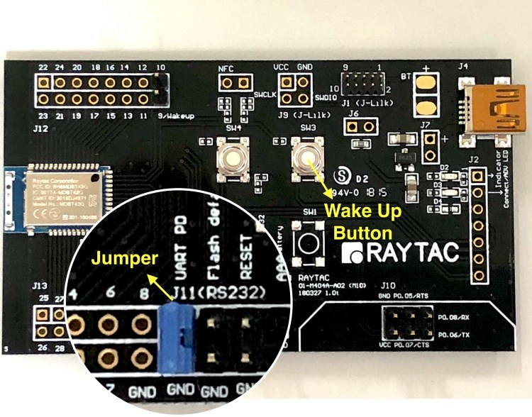

Hardware Set Up
- MDBT42Q-ATM Demo Board or MDBT42Q-AT Demo Board Board (UART default 9600,n,8,1 no flow control).
- CP2102 USB-TTL Board


Software Set Up
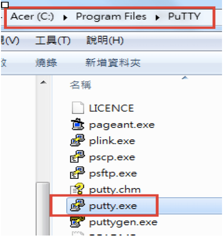
1. PC Install Putty (e.g. download putty-64bit-0.70-installer.msi) or Docklight
2. Insert CP2102 board to PC


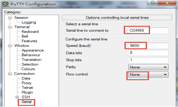
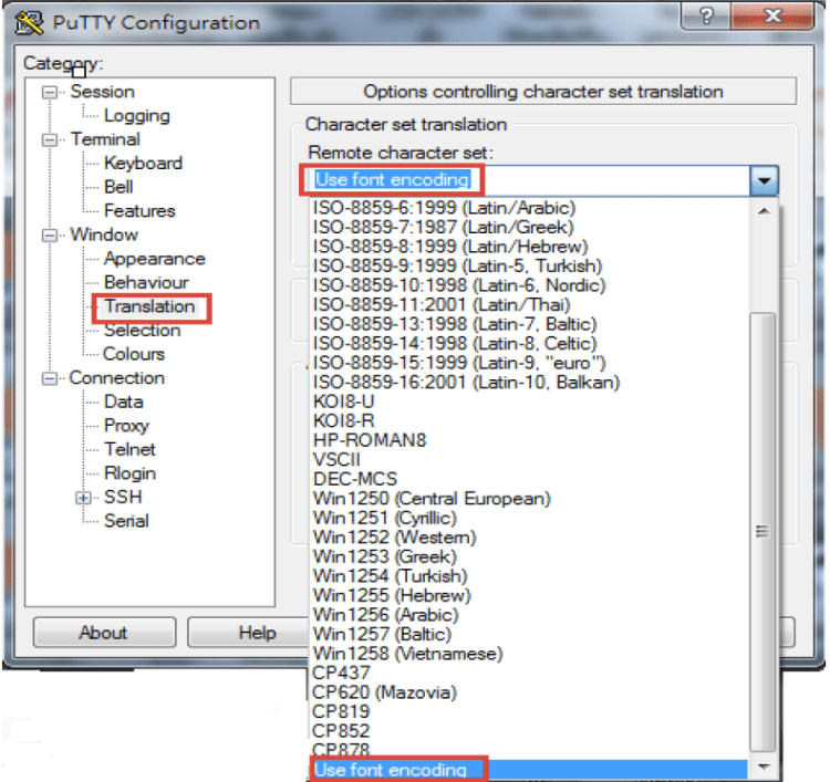
3. Run Putty and setup, then save to Test


4.Exit Putty and run Putty again, Select Test and then click Open,

5. Input AT?NAME at command and press Enter,

6. Press Enter to get board default device name “Raytac AT-UART"

Developers may find out more detail information about the command list or and demo board user guide by link provided in below.
Peripheral / Slave Role (MDBT42Q-AT & MDBT42Q-PAT)
MDBT42Q-AT &MDBT42Q-PAT Demo Board User Guide
MDBT42Q-AT &MDBT42Q-PAT (nRF52810 AT Command Module) Spec Sheet
Central / Master Role (MDBT42Q-ATM & MDBT42Q-PATM)
MDBT42Q-ATM &MDBT42Q-PATM Demo Board User Guide
MDBT42Q-ATM &MDBT42Q-PATM (nRF52832 AT Command Module) Spec Sheet

Hello,
This link above (AT Command Module Spec Sheet (Please Click Me)) does not work for me. Can you enable it, please?
Also, which Nordic SoftDevice must I program for the smallest MDBT42V modules to be able to control them from an external MCU by using AT commands?
Many thanks,
Gabriel
讚讚