[CA, USA/Taipei, Taiwan]
Raytac Group, a worldwide leader in wireless modules, wireless solutions, and a Nordic-recommended third-party module manufacturer, announces the upcoming release of the AN54LM series modules, built on Nordic’s nRF54LM20A/nRF54LM20B SoC.
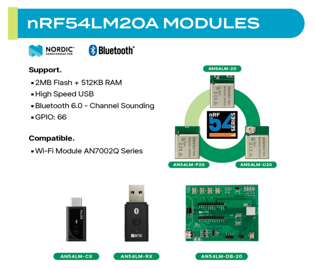
The series comes in a compact form factor of 9.9 x 13.3 x 2.0 mm (0.39 × 0.52 × 0.08 inches) and offers 3 antenna variants:
– Ceramic chip antenna: AN54LM-20. See full product details
– PCB trace antenna: AN54LM-P20. See full product details
– u.FL connector for external antenna: AN54LM-U20. See full product details
The Max output power is +8 dBm and data rates up to 4 Mbps for low-latency applications.
Powered by the nRF54LM20A/B, AN54LM features a high-end dual-core architecture (Arm Cortex-M33 + RISC-V) with up to 2 MB Flash and 512 KB RAM, enabling complex, memory-intensive applications.
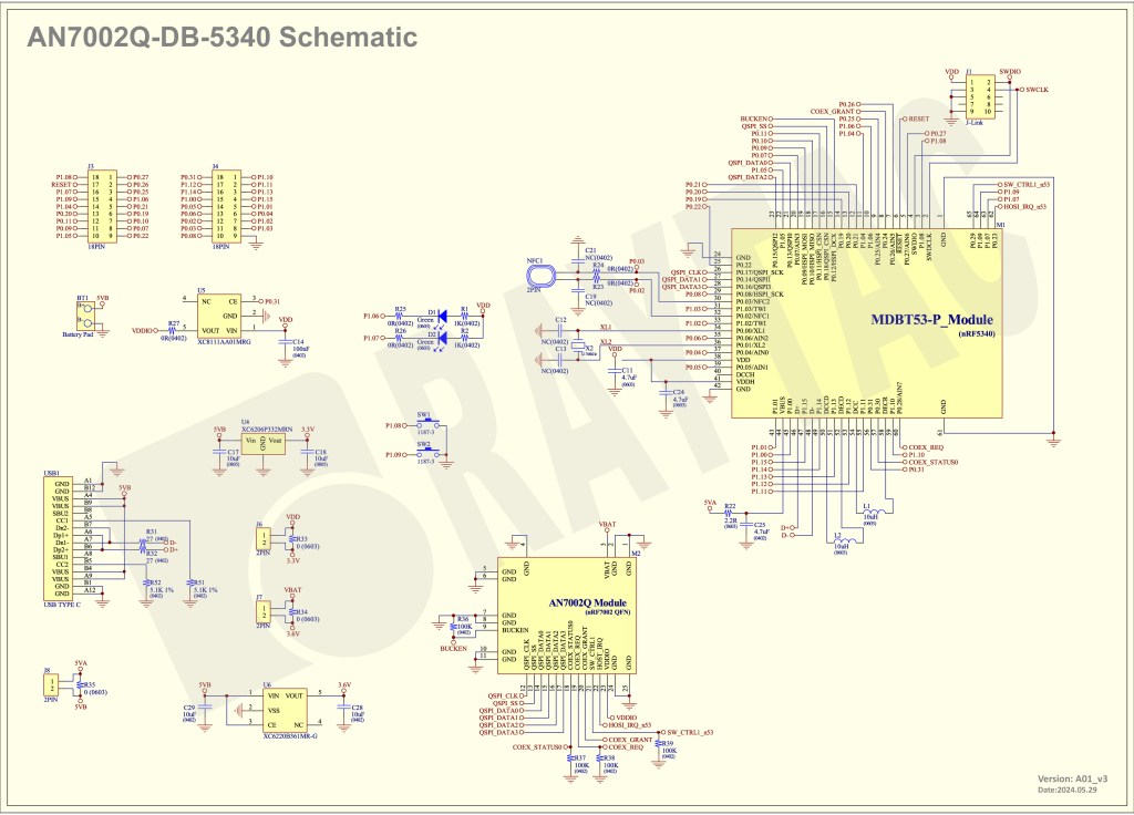
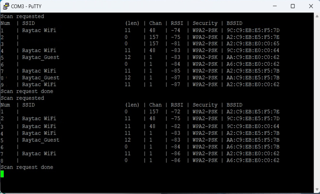
In addition to its multi-protocol support, AN54LM series is compatible with the AN7002Q series Wi-Fi modules(nRF7002 solution) to enable Wi-Fi expansions.
Know more about the AN7002Q series here.
On the security side, AN54LM series’ hardware and firmware align with EU Cyber Resilience Act (CRA) security principles, helping ensure trusted device operation and lifecycle security.
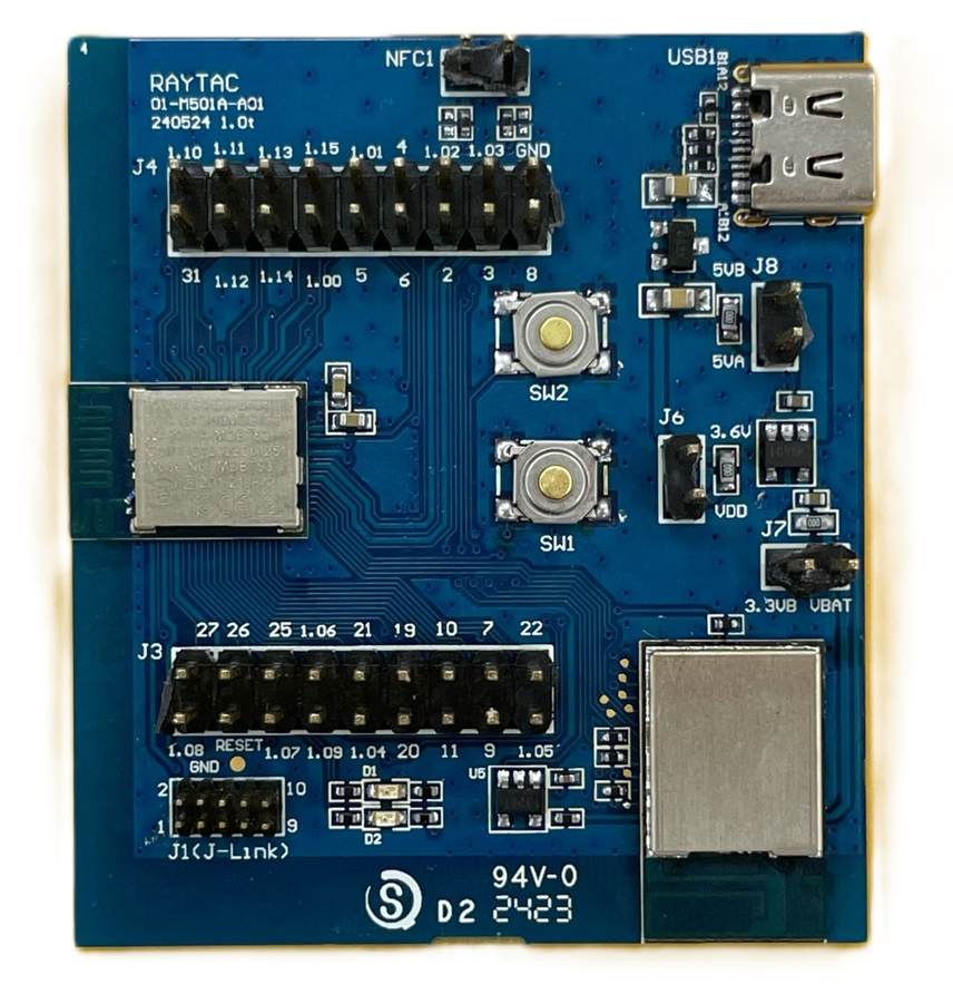
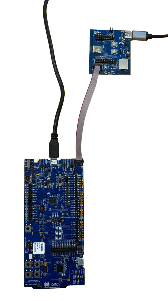
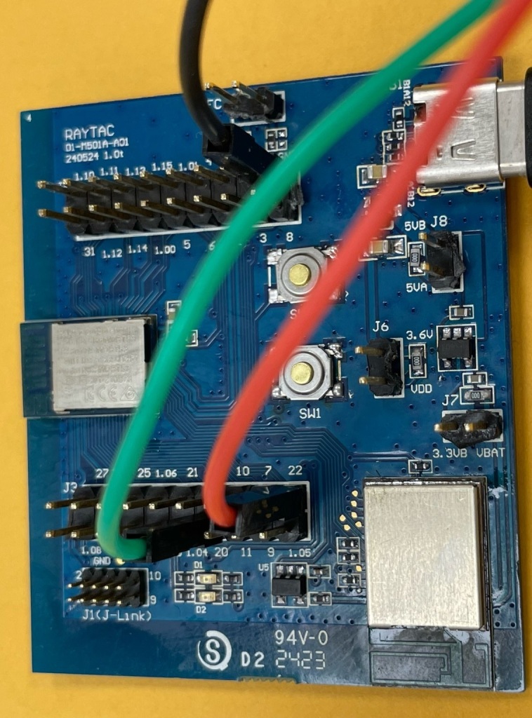
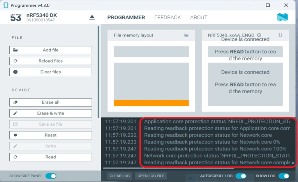
Alongside modules, Raytac is also working on developing a complete ecosystem, including evaluation boards(Dev Kits) and USB dongles, providing a practical pathway to faster time-to-market for embedded engineers.
“The AN54LM series represents Raytac’s/abietec’s continued commitment to delivering high-quality wireless modules based on Nordic’s solutions."
“By combining advanced processing capabilities, multi-protocol support, and a comprehensive development ecosystem, we aim to help all engineers innovate and reduce time-to-market.”
— Lyon Liu, CEO, Raytac Group.
Access Raytac’s full nRF54LM20A/B Products here:
https://www.raytac.com/product/index.php?index_m1_id=81&index_m2_id=107
Key Features
| Category | Specification |
| Size | 9.9 × 13.3 × 2.0 mm (0.39 × 0.52 × 0.08 inches) |
| Antenna Options | Chip antenna, PCB antenna, u.FL (external antenna) |
| Bluetooth® Certification | Bluetooth® 6.0 certified |
| Target Certifications | FCC, IC, UKCA, CE, TELEC (MIC), KC, SRRC, NCC, RCM, WPC |
| Memory | 2.0 MB Flash / 512 KB RAM |
| GPIOs | 66 |
| Processor | 128 MHz Arm® Cortex™-M33 + 128 MHz FLPR RISC-V coprocessor (both with TrustZone®) |
| Security | Enhanced security aligned with EU Cyber Resilience Act (CRA) requirements |
| Interfaces | High-speed USB, High-speed SPI, SPI, UART, I²C, I²S, PDM, PWM, TDM, ADC, NFC |
| Operating Temperature | -40°C to +85°C |
| Standard Protocol | Bluetooth® LE (incl. Channel Sounding), ANT+, Zigbee, Thread, Matter, Amazon Sidewalk |
| Proprietary Protocol | 2.4 GHz proprietary protocols with up to 4 Mbps data rate |
| Wi-Fi Expansion | Compatible with AN7002Q series (nRF7002 solution) |
Samples of AN54LM series modules are est. available in Q2 2026.
Please subscribe to Raytac’s WordPress blog: https://raytac.blog for more upcoming information.
Welcome to send an inquiry to any of the below links:
Raytac Corporation contact form: https://www.raytac.com/contact/
Raytac Corporation mailbox: sales@raytac.com
abietec Inc. contact form: https://www.abietec.com/contact
abietec Inc. mailbox: service@abietec.com
to discuss how Raytac/abietec can support your project.
Let’s keep in touch!
Edited by Business Development Manager: Tony Yin
Raytac Corporation 勁達國際電子股份有限公司 / Raytac Corporation (USA) / abietec Inc.
A Bluetooth, Wi-Fi, and LoRa Module Maker/ODM & OEM Manufacturer based on
Nordic nRF54; nRF53: nRF52; nRF51; nRF7002
Infineon: CYW55912
NXP: RW610, RW612
Semtech: SX1262
Bluetooth Specification: BT6 ; BT5.4 ; BT5.3 ; BT5.2.
Wi-Fi Specification: Wi-Fi 6
LoRa Specification: LoRaWAN
Zephyr Project Silver Member
All products are FCC/IC/CE/Telec/KC/RCM/SRRC/NCC/WPC/RoHS/Reach Certified.
Tel: +886-2-3234-0208(TW)/+1-626-328-3827(USA)