Raytac’s AN54LQ & AN54LV modules, powered by Nordic Semiconductor’s nRF54L family SoCs, come in multiple form factors and antenna options, ensuring your seamless integration into compact, RF-sensitive, or performance-driven designs.
Whether you need a: ☑ Chip antenna; ☑ PCB antenna; ☑ u.FL connector; ☑ Antenna Pin,
Or you want Small, Smaller, or Smallest, we always have a solution that fits best! *All products are pre-certified with FCC, IC, CE, UKCA, Telec, KC, SRRC, NCC, RCM, WPC.
Raytac has advanced the dev kit version of bundle offer – WIFI+BLE: AN7002Q-DB- 5340-M with an on-board flash memory(MX25R64) to create easy evaluation for Wi-Fi project developments.
[January 2026 Update] In this article, we will talk about: Project WITH External Flash MX25R64(8MB) applied – Connecting through SPI between nRF5340 module: MDBT53-1M(BLE) & nRF7002 module: AN7002Q(WIFI) – Connecting through QSPI (XIP) between MDBT53-1M and external memory MX25R64
Table of Content———————————————————————————————————
Hardware Set Up A. Project WITHOUT External Flash MX25R64 needed B. Project WITH External Flash MX25R64 needed
Software Resources & Preparations
Firmware Build & Compile A. Project WITHOUT External Flash MX25R64 needed B. Project WITH External Flash MX25R64 needed
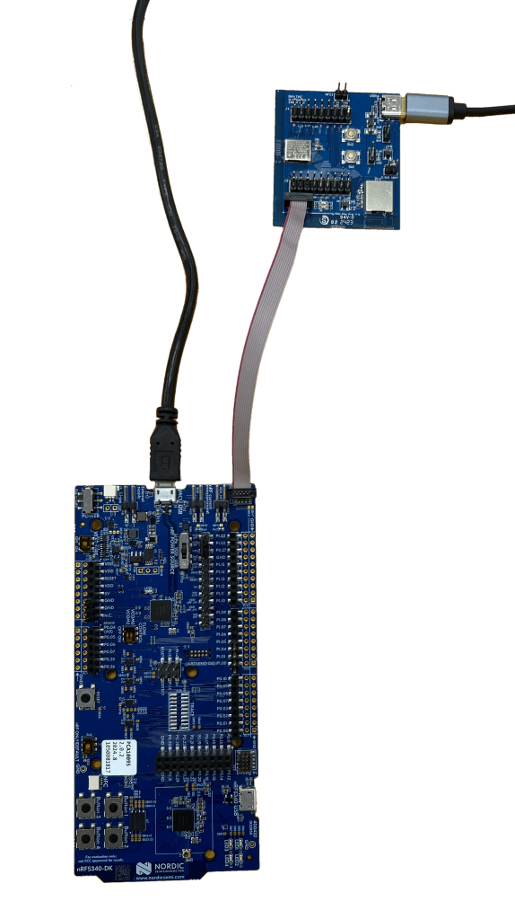
Note: Pease make sure to have both “Nordic nRF5340-DK” and “AN7002Q-DB-5340-M”connected and running during the WIFI+BLE (nRF7002+nRF5340) project development.
Hardware Network: IDC Ribbon Wire(J-Link Cable): Connect nRF5340-DK to AN7002Q-DB-5340-M USB Wire –Type C USB: Power supply to AN7002Q-DB-5340-M through USB TYPE-C USB Wire-Micro USB: Power supply to nRF5340-DK through Micro USB
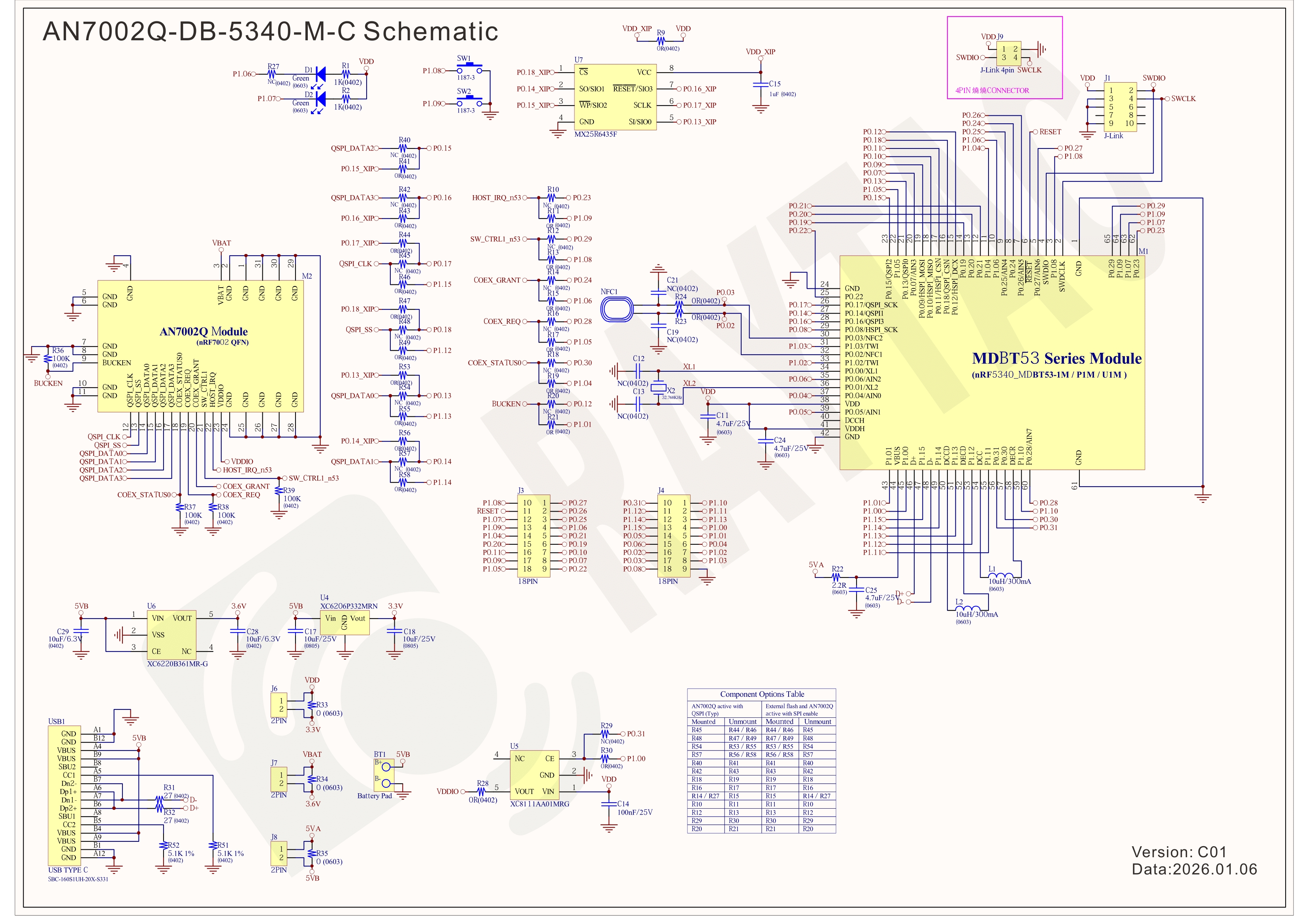
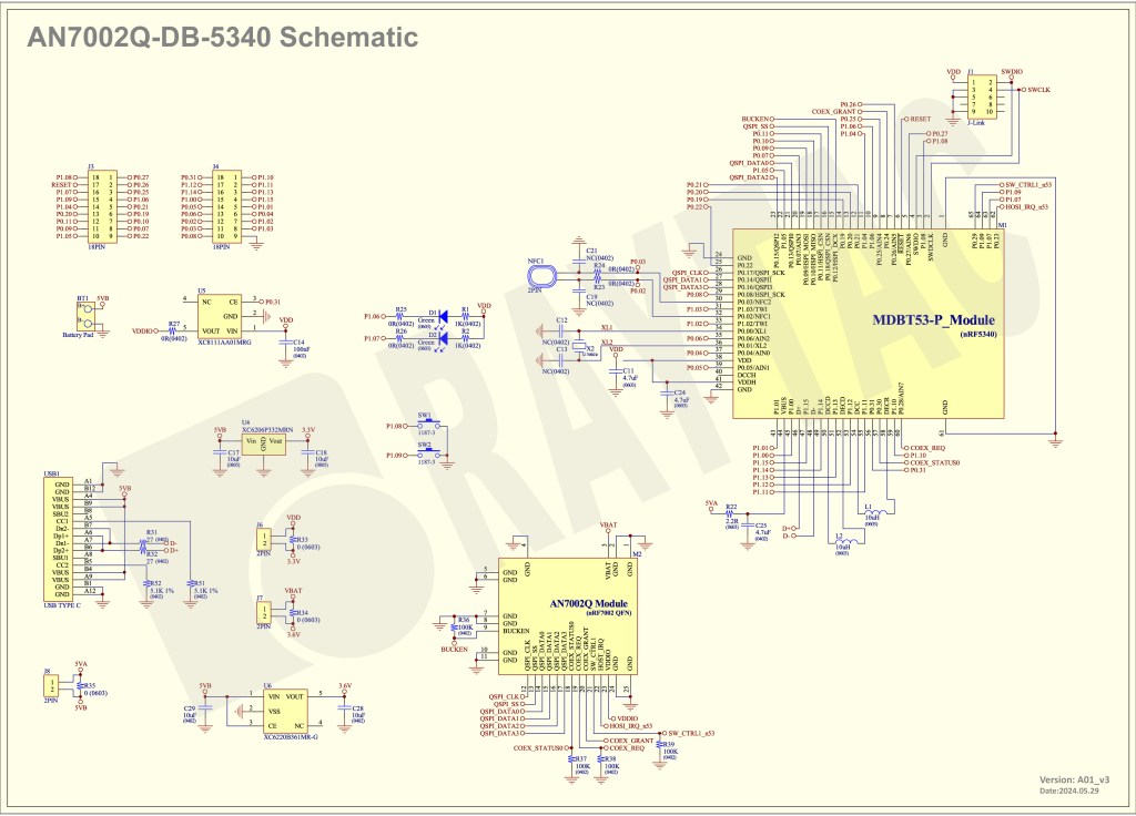
Schematic diagram of AN7002Q-DB-5340-M can be referenced for design as follows. *nRF7002 module <- SPI -> nRF5340 module *MX256R NOR Flahs <-QSPI-> nRF7002 module (Click on the image to zoom in.)
!! Important Note:!! The circuit of SW1(p1.08)/SW2(p1.09)/LED1(p1.06) on AN7002Q-DB-5340-M is NOT COMPATIBLE to Nordic WI-FI Control Pin of swctrl1(p1.08)/host_irq(p1.09)/grant(p1.06). In this case, if you’re working with external flash MX25R64 for the WIFI project, Please avoid pin SW1/SW2/LED1 usage while LED2(p1.07) remains available as normal usage. For the PCB design of end product/end device(mounted with AN7002Q & MDBT53 modules), the switch & LED should be configured to be: SW1(p0.23)/SW2(p0.24)/LED1(p0.28).
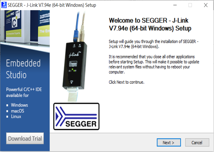
Step 1: Prepared with the latest version of nRF Connect for Desktop, using Windows 64-bit – 5.2.0 Step 2: Prepared with the latest version of Command Line Tools, using Windows X86 64 – 10.24.2
**Note: SEGGER J-LINK Upgrade message might pop up while you’re doing above downloads.
Step 3: Locate all the necessary kits for programming in PC
3. Firmware Build & Compile After you download and set up nRFConnect SDK (NCS), you will be able to apply free VS (Visual Studio) Code IDE as firmware programming tool.
The below example uses NCS v3.1.1 and runs the program under: C:\ncs
Step 1: Start with a Wi-Fi Scan project and run the program under: C:\ncs\v3.1.1\raytac <<Create a new application and Copy a sample>>
Step 2: Select SDK v3.1.1 to copy the sample
Step 3: Select example by entering keyword: wifi scan(Wi-Fi Scan)
Step 4: Enter application location: C:\ncs\v3.1.1\raytac and name the project as: wifi_scan_uart_dfu
Step 5: Open an existing application and find the registered project: wifi_scan_uart_dfu
Step 6: How to activate the Devicetree setting of Wi-Fi nRF7002 and Create file:nrf5340dk_nrf5340_cpuapp.overlay Code example is as follows: / { chosen { aliases { /delete-node/ leds; /delete-node/ buttons; }; };
Step 7: It is required to do MCUBoot before working with DFU using External Flash Please do the code configuration in sysbuild.conf as following reference code.
SB_CONFIG_BOOTLOADER_MCUBOOT=y # DFU with UART SB_CONFIG_MCUBOOT_MODE_SINGLE_APP=n
# DFU with external flash SB_CONFIG_PM_EXTERNAL_FLASH_MCUBOOT_SECONDARY=y
Step 8: It is required to doMCUMGR before working with DFU over UART Please do the code configuration in prj.conf as following reference code.
# Enable QSPI driver for Application CONFIG_NORDIC_QSPI_NOR=y
# Enable mcumgr DFU in application CONFIG_MCUMGR=y CONFIG_NET_BUF=y CONFIG_ZCBOR=y CONFIG_CRC=y
# Enable mcumgr management for both OS and Images CONFIG_MCUMGR_GRP_OS=y CONFIG_MCUMGR_GRP_IMG=y CONFIG_FLASH=y CONFIG_IMG_MANAGER=y CONFIG_STREAM_FLASH=y CONFIG_FLASH_MAP=y
# Configure MCUMGR transport to UART CONFIG_MCUMGR_TRANSPORT_UART=y CONFIG_BASE64=y
Step 9: Add with MCUBoot setting , and create a root for sysbuild ; Build with file mucboot.overlay & file mcuboot.conf
9A. To the File: mucboot.overlay &mx25r64 { status = “okay"; };
Step 10: Create a VERSION file by referencing the following code when testing DFU over UART. VERSION_MAJOR = 99 VERSION_MINOR = 0 PATCHLEVEL = 0 VERSION_TWEAK = 0 EXTRAVERSION =
Step 14: Generate a Merged.hex file after compiling the program
Step15: You can choose Build/Debug/Flash under ACTIONS during development << Build >>
<< Debug >>
<< Flash >>
Step 16: Go to ACTIONS >> Memory report to check the memory partitions.
Now you can see partitions available in the system. mcu_secondary has already been located in MX25R64 flash memory.
4. Test/Validate DFU Process & WIFI SCAN After the firmware programmed to MDBT53 module on board, we use the USB to UART adaptor board for connecting AN7002Q-DB-5340-M through: A. MCUMGR UART to PC and through: B. WiFi Scan UART to PC respectively. Note: We suggest you finish connecting A. and B. before running tests.
Now we can run the tests.
A. DFU over UART – Using AuTerm Program 1. We can locate Image version=V99.0.0 under the current VERSION file
It also indicates Image version: 99.0.0 in MCUmgr-Slot 0.
2. Try to modify the file version from V99 to V100 under VERSION file: VERSION_MAJOR = 100
VERSION_MINOR = 0
PATCHLEVEL = 0
VERSION_TWEAK = 0
EXTRAVERSION =
And go with “Pristine Build”
3. We’re about to run DFU over UART , Please DO NOT do “Flash” or “Erase”.
Proceed with “Force reboot”
4. It’s now Version 100.0.0 in Slot 0 under MCUgr ⭢ DFU over UART successfully done!
Before it was Version 99.0.0 in Slot 1 under MCUgr.
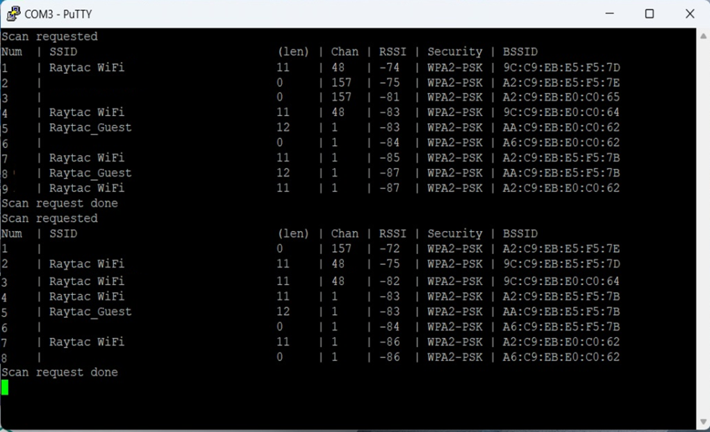
B. WIFI SCAN – PuTTY Console WIFI SCAN credentials can be located under PC Console – PuTTY.
In this article, Stanley Huang, MSc, Deputy Manager of Firmware Development at Raytac, shares insights on how Raytac’s modules and development kits strengthen the Zephyr ecosystem.
[Stanley Huang, New Taipei City] When we talk about open-source platforms like Zephyr RTOS, most people immediately think of major chip manufacturers such as ST Micro, NXP, or Nordic. But to me, what truly makes Zephyr famous amongst the developer community is through modules that developers can actually touch: those they can instantly plug in and start using right away. In these terms, Raytac is one of the most underrated and important contributors in this ecosystem.
Raytac Modules Make Zephyr More Accessible Instead of being a chip vendor, we specialize in producing high-quality, globally certified modules – especially Bluetooth and Wi-Fi modules based on Nordic chipsets, such as the AN7002Q, AN54LQ, AN54LV, MDBT53, MDBT50Q, and MDBT42Q. All these modules are already certified with Regional RF compliances(FCC, IC, CE, KC, etc.) and the latest Bluetooth Specifications, offering developers the assurance of “plug and play” and “production-ready” solutions. We assure that our modules have become one of the easiest platforms for Zephyr developers to test BLE functionality.
I paired Zephyr with Raytac’s MDBT50Q-DB-40 development board when I first applied Zephyr in a BLE Peripheral project . With a simple west build -b nrf52840dk_nrf52840 followed by flashing the firmware using J-Link or nRF Connect for Desktop, the BLE beacon immediately showed up on my phone. Clean, simple, noise-free, and developer-friendly – that’s Raytac’s style.
Modules play an invaluable role in product development Many would say Raytac only makes modules and the real core is still Nordic’s SoC. But I believe that in an open-source system like Zephyr, the hardware that helps your project runs first is that which contributes the most. Our Zephyr-registered development kits eliminate the hassles of manual soldering, regulatory certification, and antenna design, allowing engineers to fully focus on developing applications based on Zephyr. They can run Zephyr’s BLE peripheral, central, GATT, and HCI samples directly on the Raytac kits that act as a one-stop hardware solution. In many ways, Raytac has pushed Zephyr’s usability a significant step forward.
Raytac Also Expands Zephyr’s Application Horizon Many of Raytac’s modules are ultra-compact- ideal for wearables, smart sensors, and low-power beacons…etc. These are the scenarios where Zephyr excels, and Raytac’s modules provide the physical platform to enable companies to build their “dream devices". When running Zephyr on a tiny module like the AN54LV-15(Product Link), developers will be amazed that something smaller than a piece of corn kernel can run a full RTOS, manage the BLE stack, trigger timers, drive I2C sensors, and even connect to the cloud, all by itself. This combination doesn’t just make development easier – it inspires developers to realize that: “they can build their projects using Raytac’s hardware.”
Raytac may not be the star, but we’re always ready for you On Zephyr’s main stage, companies like Nordic, STM, and Intel take the spotlight, but Raytac plays an essential supporting role – supporting the performance from behind the scenes. We offer stable, high quality, and low-power platforms, giving every line of Zephyr code a place to run and every feature a cornerstone. Our greatest value lies in helping developers skip antenna design and RF interference concerns – so they can jump right into the Zephyr ecosystem with ease.
Our products deliver the reliability you need and the efficiency you expect.
To help you quickly get started with Raytac’s AN7002 Nordic WiFi module and nRF5340 module, here’s a simple guide on how to set up the development and programming environment using AN7002Q-nRF5340 Demo Board(AN7002Q-DB-5340)and nRF5340 DK.
This article will cover the 4 sections below: 1. Hardware setup 2. Software Development Kit and Environment setup 3. Programming/Development 4. Flashing/Uploading firmware
1. Hardware Setup 1 x Nordic nRF5340-DK: PCA10095(2.0.0) 1 x Raytac AN7002Q-DB-5340 1 x IDC Cable 1 x USB-Micro USB Cable 1 x USB-Type C USB Cable
*Note: You need to use both the “Nordic nRF5340-DK” and “Raytac AN7002Q-DB-5340 demo board” together for programming and development. *
Steps to connect the hardware:
Connect J-Link on Nordic DK to AN7002Q-DB-5340using IDC Cable
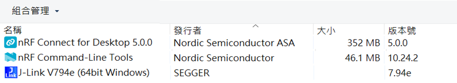
After the installations are completed, you can see the following applications under the:
“Programs and Features" section in the Control Panel.
3. Programming/Development
nRF Connect SDK (NCS) supports development using the free VS (Visual Studio) Code IDE. Here’s how to select and install the NCS SDK version (nRF Connect SDK vx.x.x):
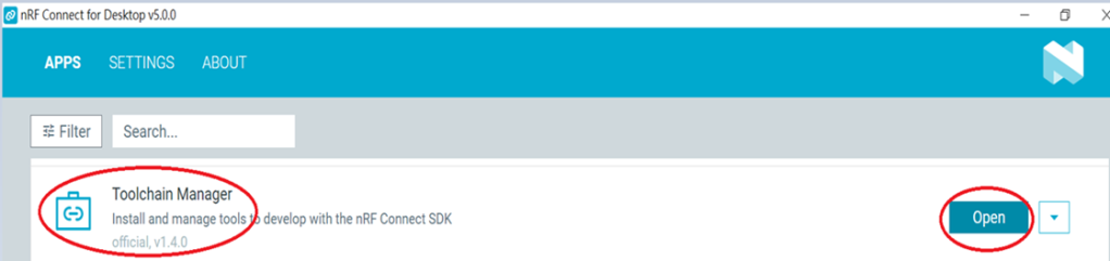
Step1.
Open “nRF Connect for Desktop” → Choose “Toolchain Manager” → then click” Open”
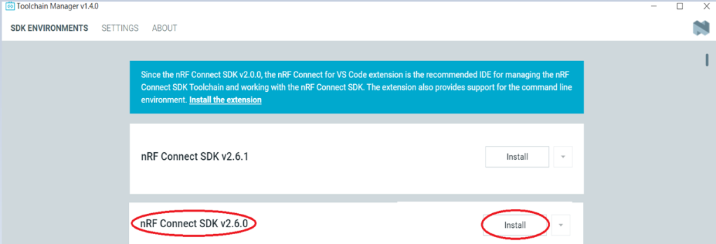
Step2.
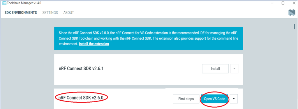
You’ll see a list of nRF Connect SDK versions. It’s recommended to install NCS v2.6.0 or later. Here, we use NCS v2.6.0 as an example.
Step3.
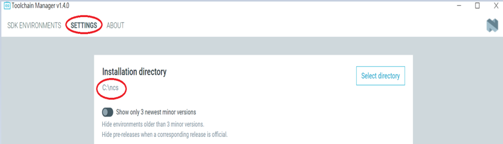
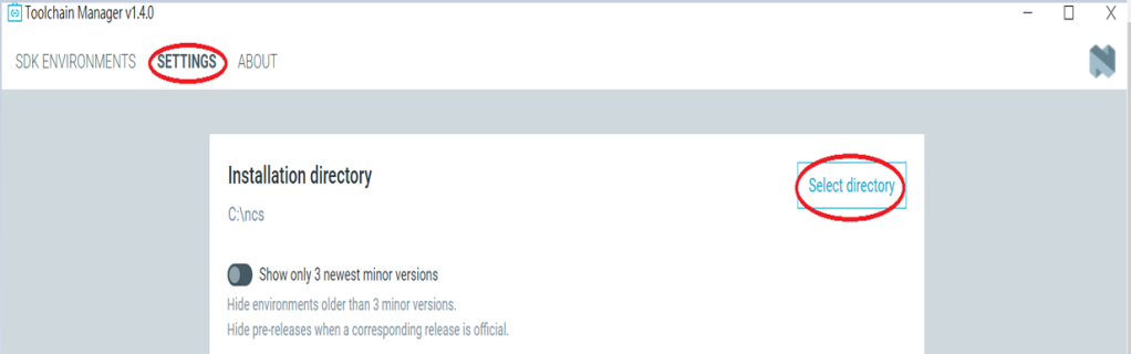
Before installing NCS v2.6.0, confirm the installation path (Default path → C:\ncs).
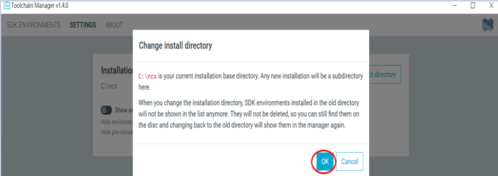
If you want to change the path, click “Select directory”, and press OK.
Step4.
After installing the nRFConnect SDK v2.6.0, click “Open VS Code”.
Step5.
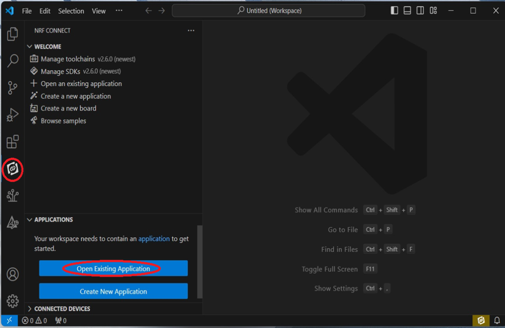
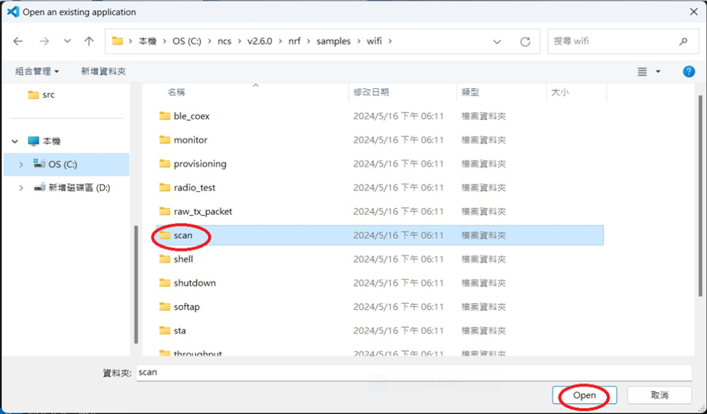
Open the Wi-Fi scan example
Step6.
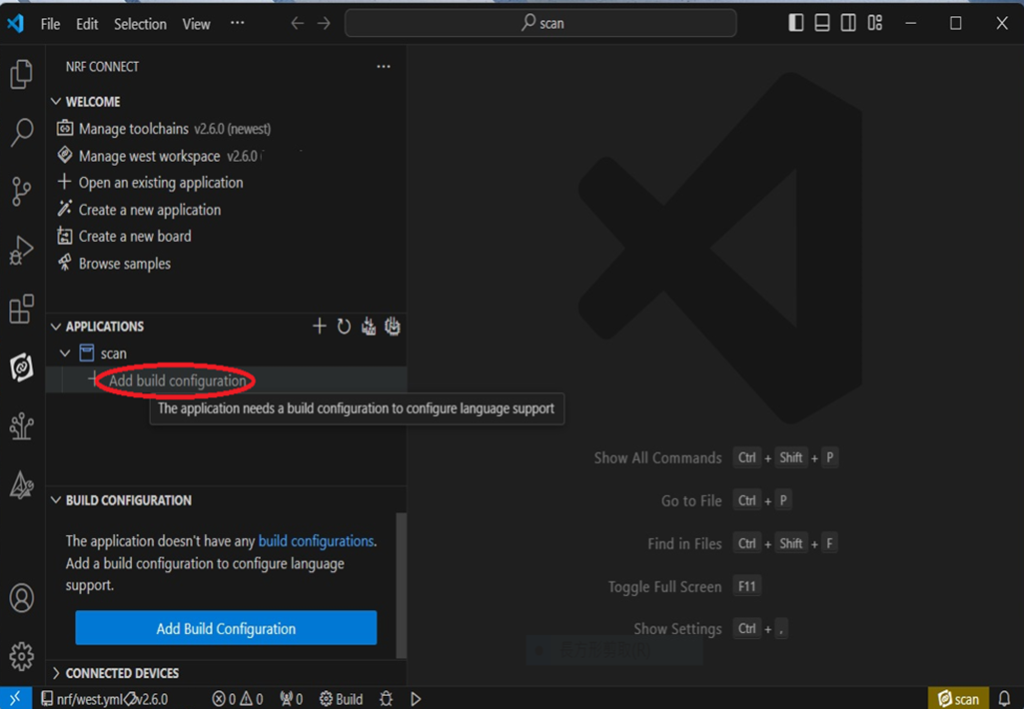
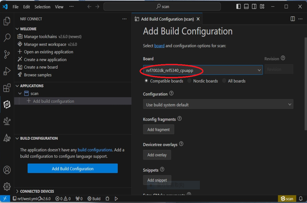
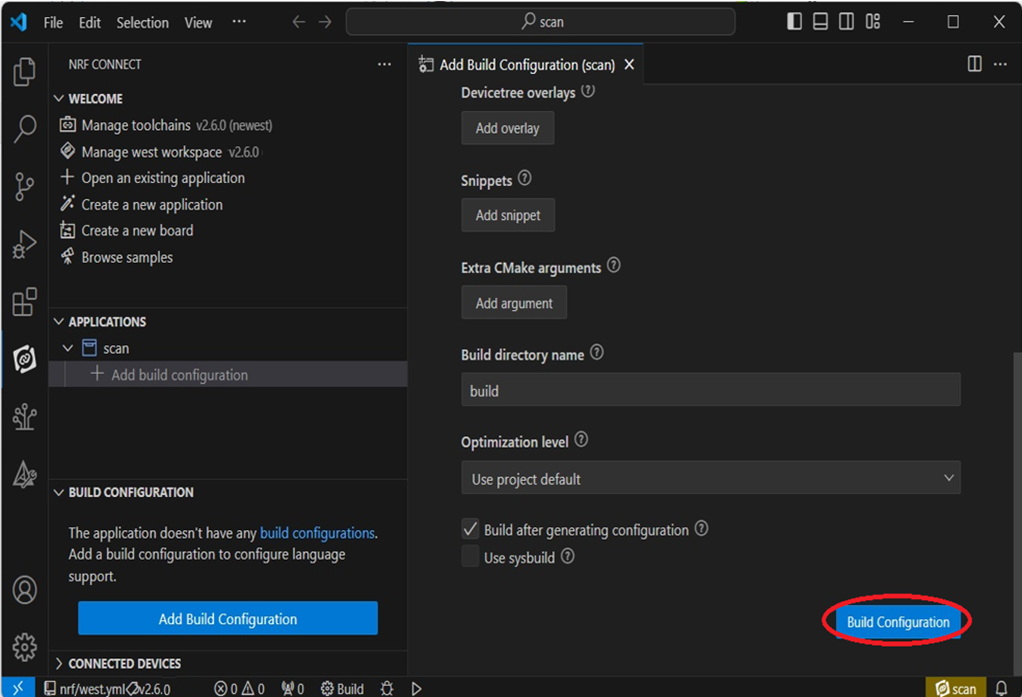
Add build configuration → select the board and compile.
Select board: nrf7002dk_nrf5340_cpuapp.
Step7.
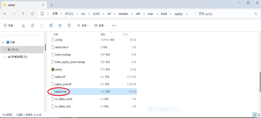
After compilation, a hex file will be generated.
Step8.
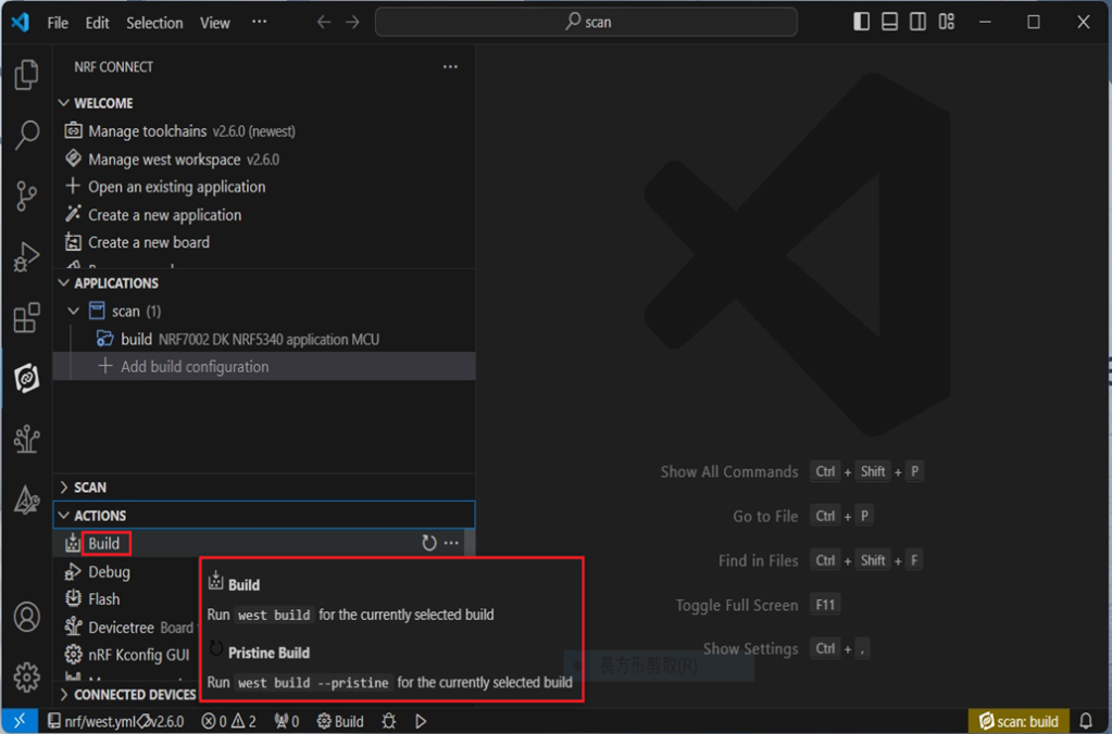
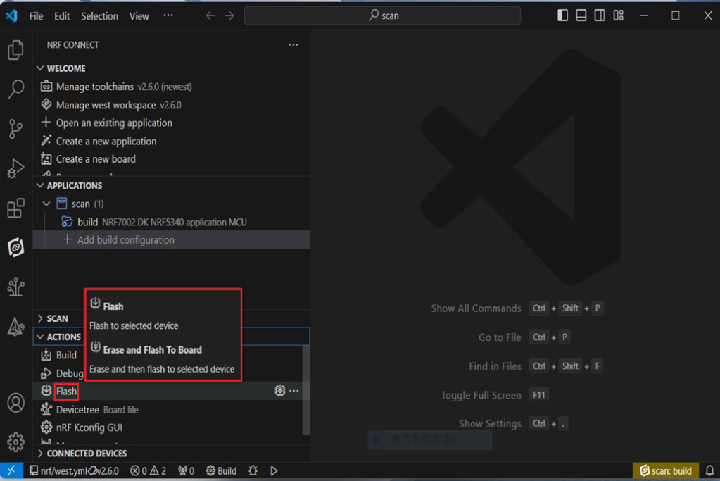
Under ACTIONS, you can choose to Build, Debug, or Flash.
Build:
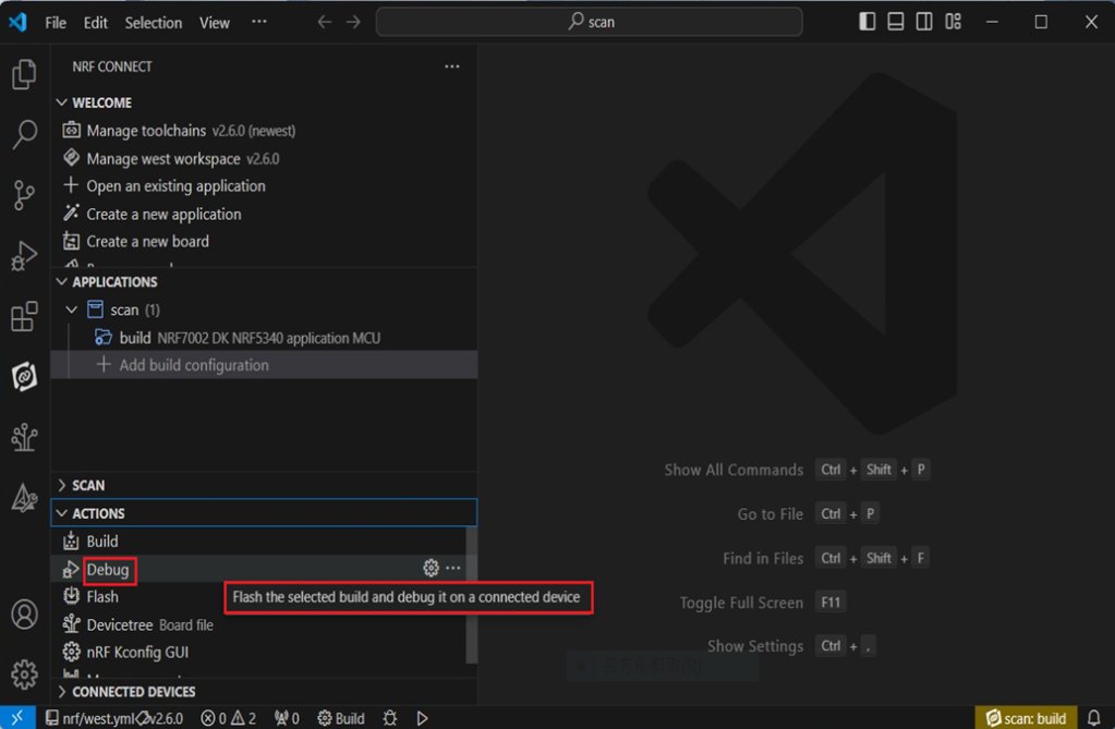
Debug:
Flash:
4. Programming
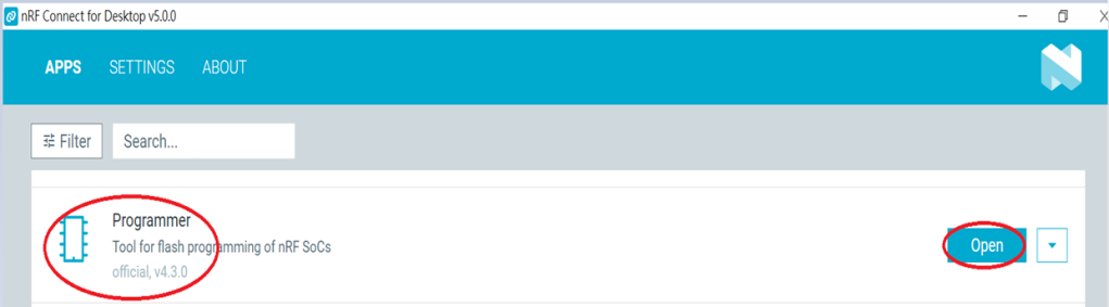
nRF Connect SDK(NCS) supports programming. You can use the “Programmer” tool to flash .hex file. Here’s how:
Step1.
Open “nRF Connect for Desktop” → Select “Programmer” → then click” Open”.
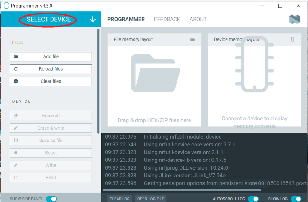
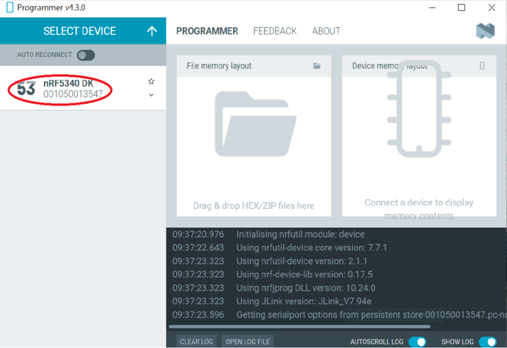
Click “Select Device”;
Since AN7002 Wi-Fi IC does not act as an MCU, we can only flash the .hex file into the MDBT53(nRF5340) BLE IC.
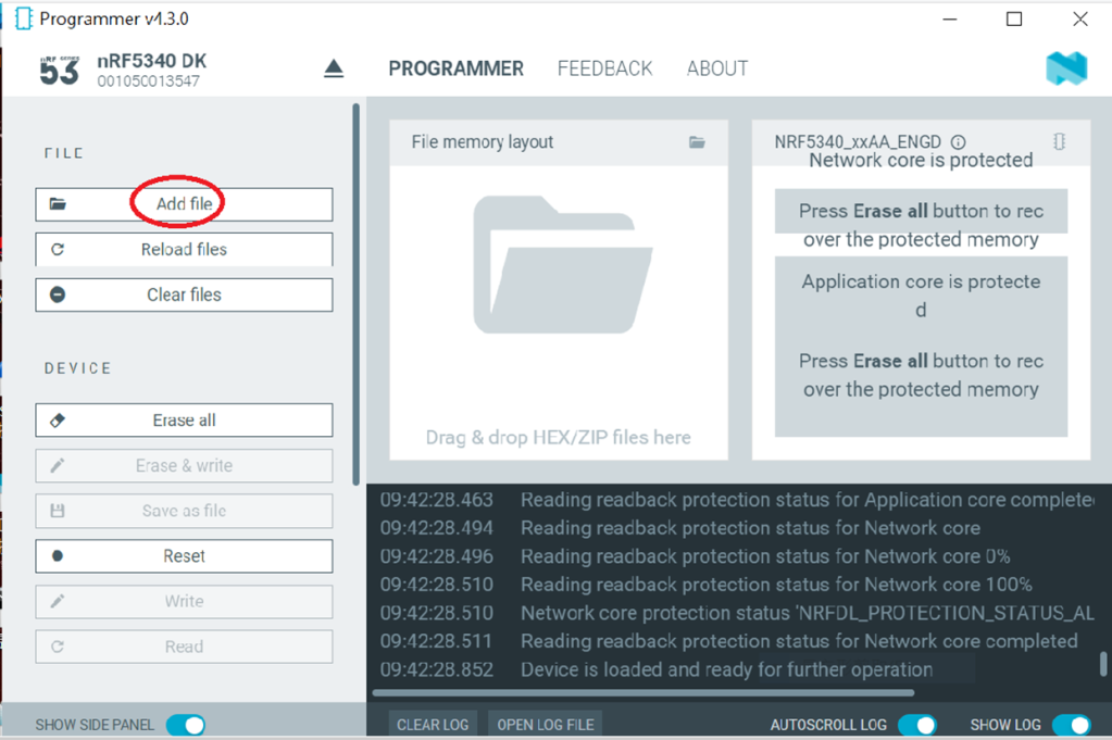
Click “Add file” to add the .hex file.
Step2.
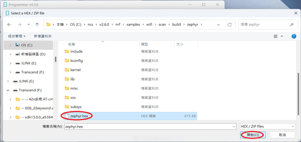
Select the .hex file you want to flash.
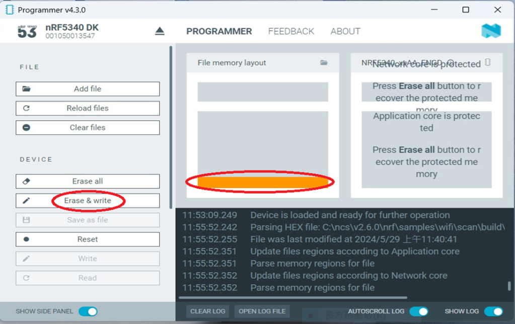
The hex file will be written into the part of the memory layout (where orange part is highlighted).
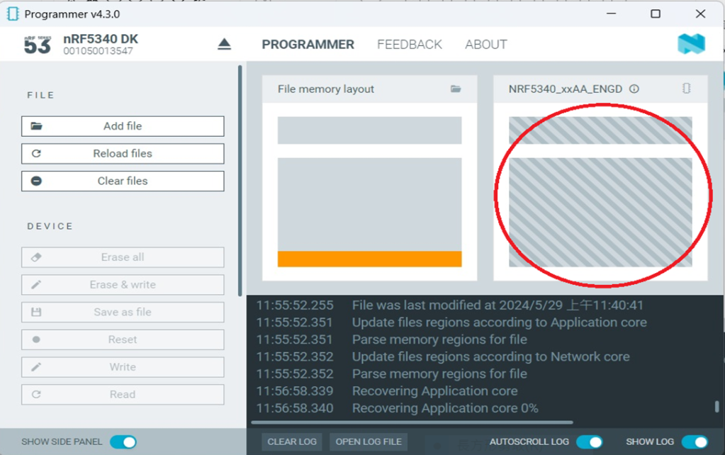
Slashes will be displayed in the circled part during the flash process.
Step3.
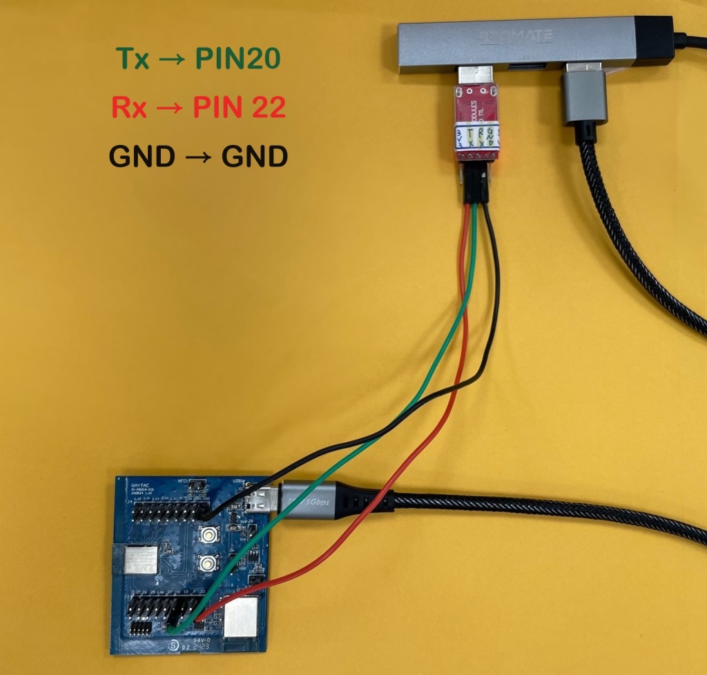
Once the flash process is completed, connect Raytac’s AN7002Q-DB-5340 development board to PuTTY.
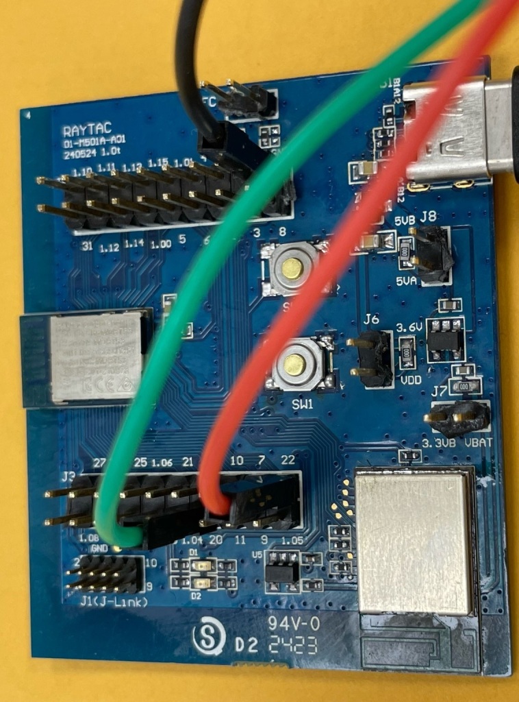
Tx to p0.20
Rx to p0.22
GND to GND
This is a closer look into the pins that will be connected.
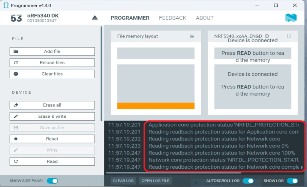
The flash process is completed when the LOG is displayed as circled below.
Check if hardware connection is successful using PuTTY.
*2024-Aug-12 update:* Before running Scan code / Station code / Shell code: You must ensure that the MAC address has already been programmed into the module. Click on this link to learn more about how to load the MAC address.
Edited by Sales Manager: Ms. Vicky Huang Technical guidance provided by R&D Manager: Mr. MW Lee Hardware environment provided by Hardware Engineer: Mr. Kyle Wang
Check out our two-part video tutorial about #Bluetooth low energy. In this tutorial, Nordic gives a developer’s introduction to Bluetooth and the development tools offered.