MDBT50Q-CX is an advanced version of Raytac’s MDBT50Q-RX(USB-A Dongle).
MDBT50Q-CX has a more compact size, equips an up-to-date Type C USB Connector, and it has a built-in open bootloader for simple DFU process.
If you’ve been developing projects using MDBT50Q-RX in the past, you can find out in this manual how MDBT50Q-CX makes firmware compiling and loading much easier than before.
If you want to load firmware into MDBT50Q-CX, no wiring is needed.
Simply plug the dongle into your device and USB DFU will be available.
MDBT50Q-CX (USB-C Dongle, nRF52840/nRF52833 solution): Product link
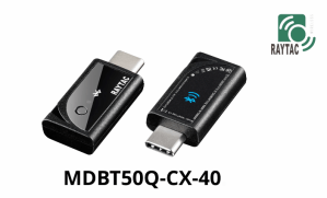
Size: 15.10 x32.85mm (0.59×1.29inches)
Table of Contents
A. Hardware intro
B. Software development environment setup
C. Firmware Implementation with NCS (nRF Connect SDK) or NRF5 SDK
D. Execute DFU (Device Firmware Update)
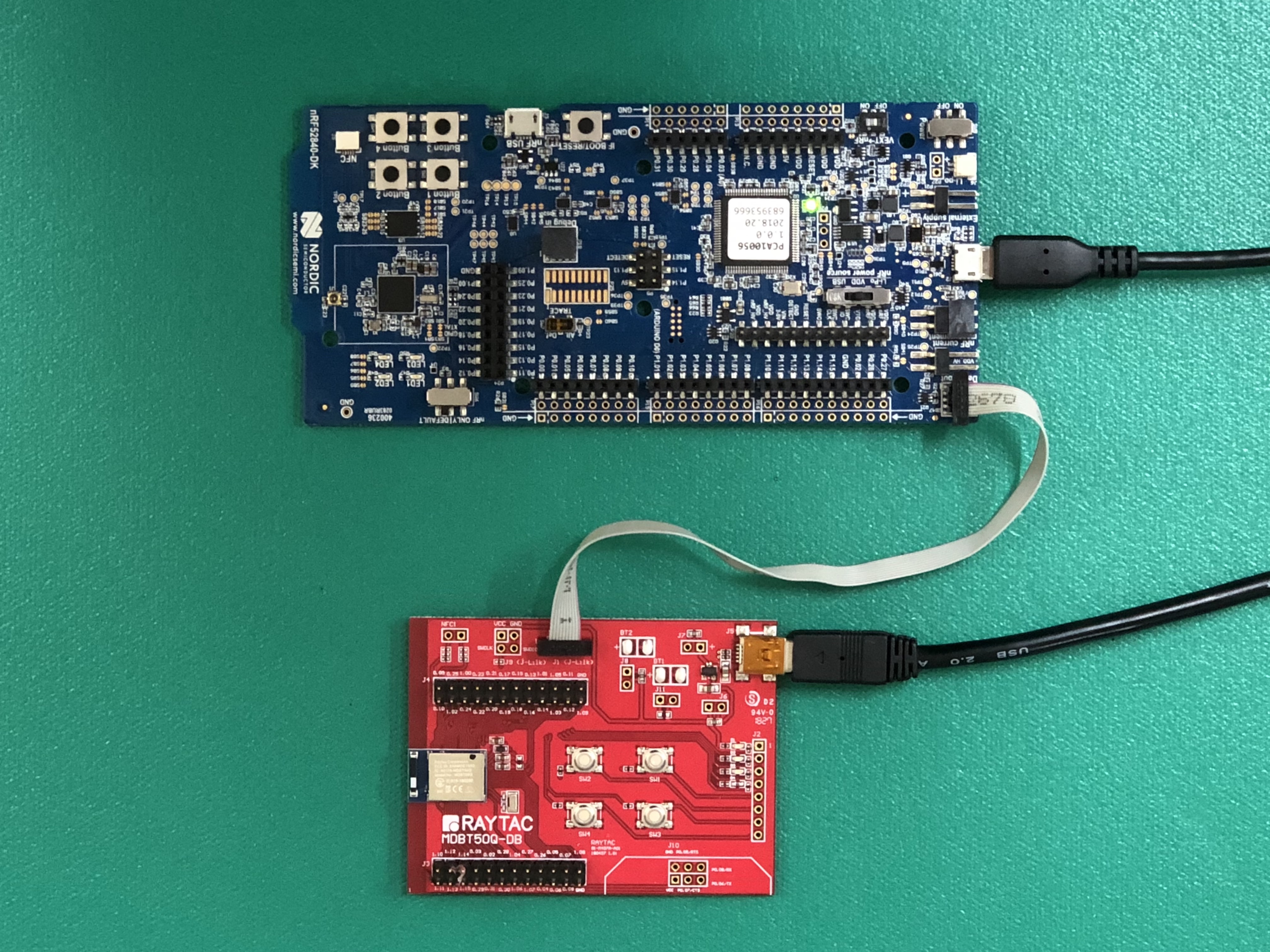
A. Hardware Intro
<Pin Allocation>

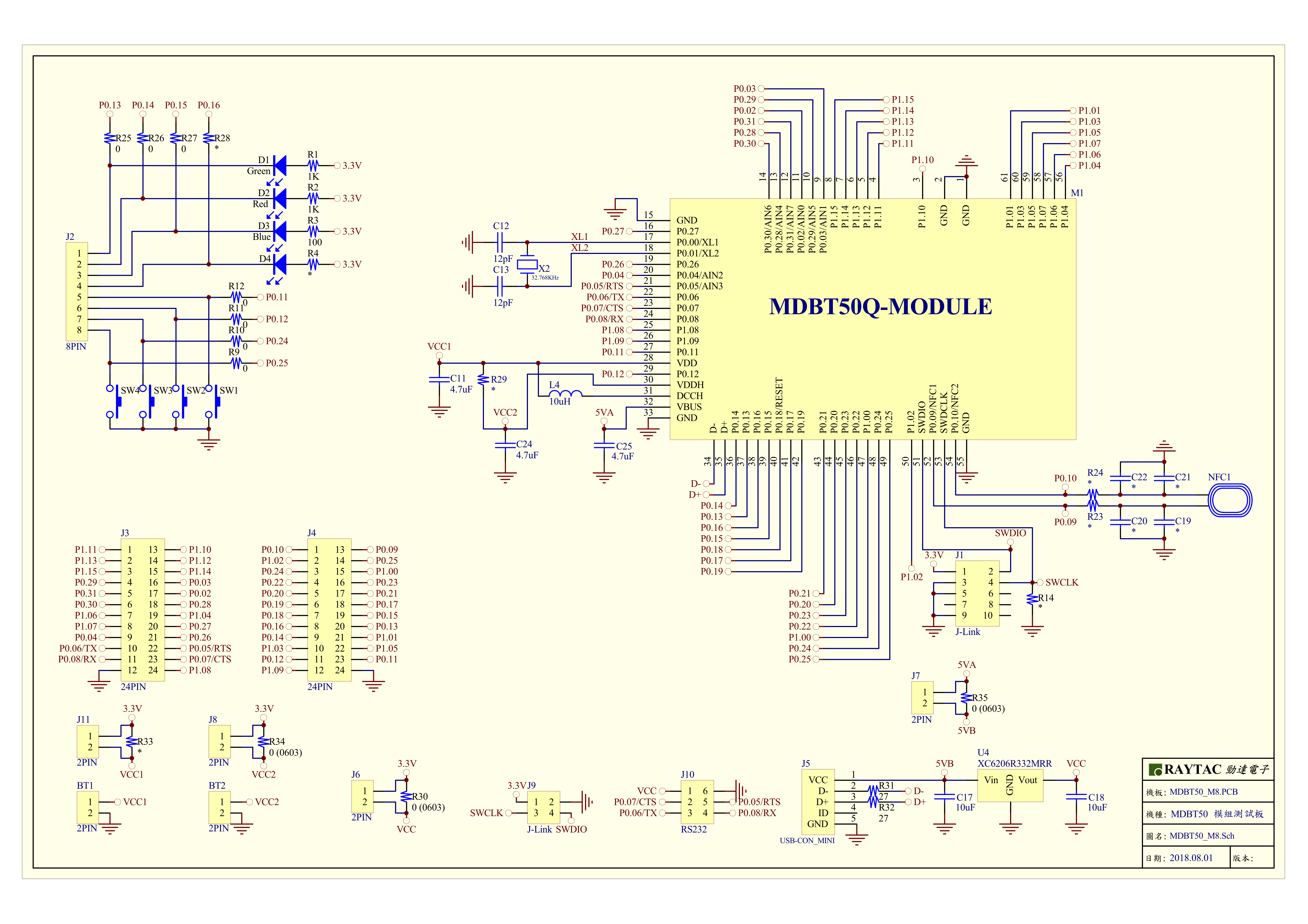
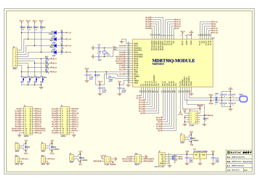
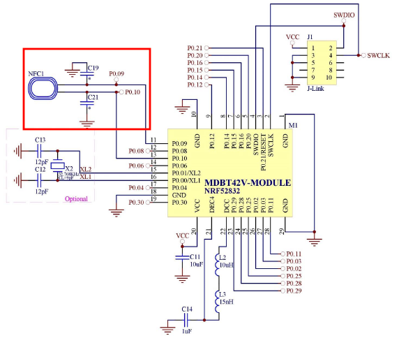
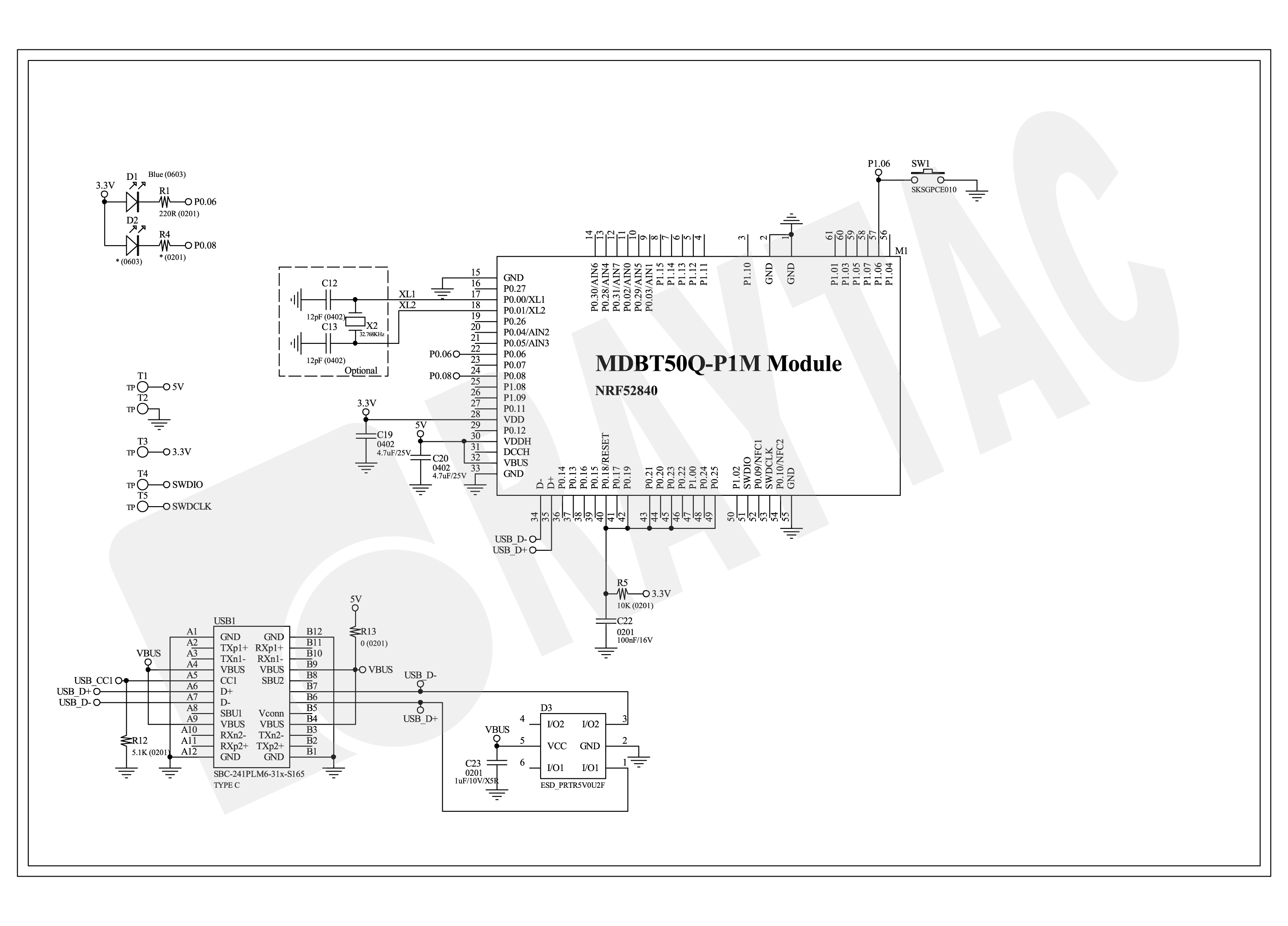
< Schematic> (Click on the image to redirect to product page for Higher resolution photo)
B. Software development environment setup
Option 1. Compile in NCS(nRF Connect SDK)
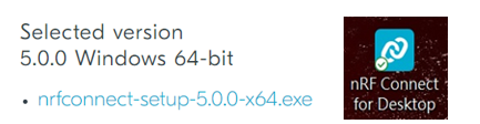
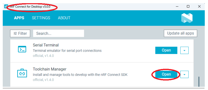
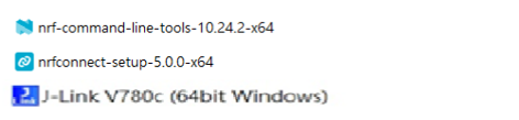
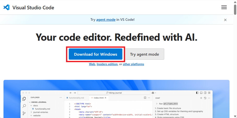
(1) Install nRF Connect for Desktop:

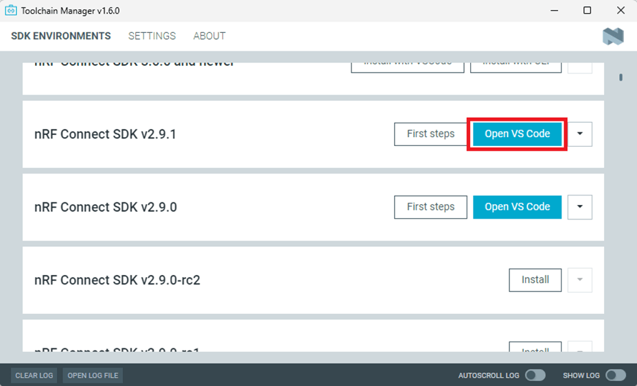
(2) Install Toolchain Manager and Programmer

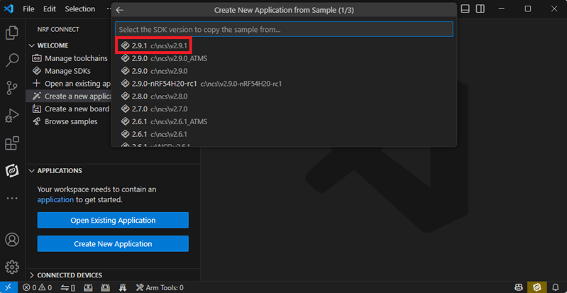
(3) Install nRF Connect SDK (NCS) → V2.6.0 is recommended.

Option2. Compile in nRF5 SDK
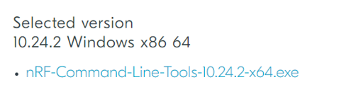
(1) Download open source nRF5 SDK (Recommend: download the latest version: 17.1.0)

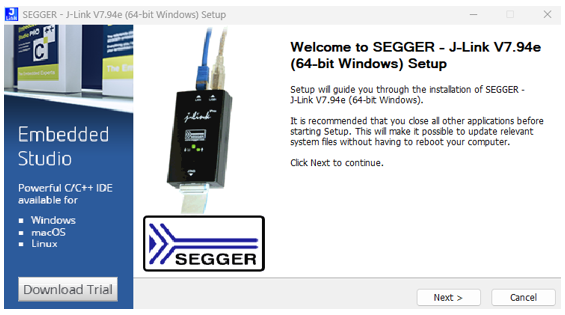
(2) Install Segger Embedded Studio v5.42a (Recommended version)
https://www.segger.com/downloads/embedded-studio/

※Welcome to contact Raytac sales team for v5.42a file of Segger Embedded Studio.
C. Implement firmware in NCS (nRF Connect SDK) or NRF5 SDK
We will use the two example codes below for this demo:
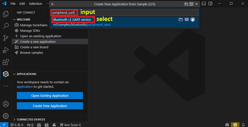
C1. NCS (nRF Connect SDK):
Example code path: \v2.6.0\nrf\samples\bluetooth\peripheral_uart
C2. nRF5 SDK:
Example code path: \nRF5_SDK_17.1.0_ddde560\examples\peripheral\usbd_ble_uart
C1. NCS (nRF Connect SDK): (Using nRF Connect SDK V2.6.0)
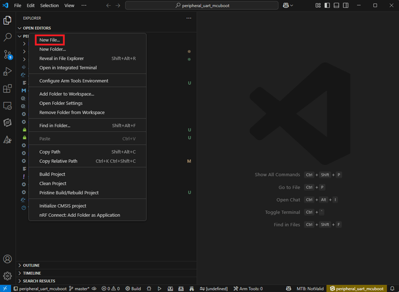
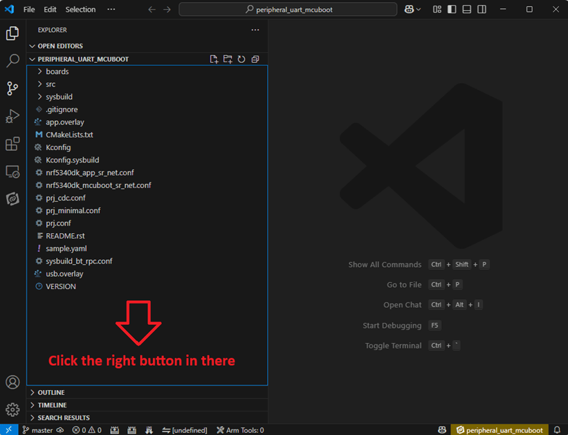
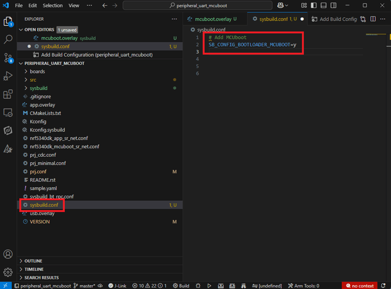
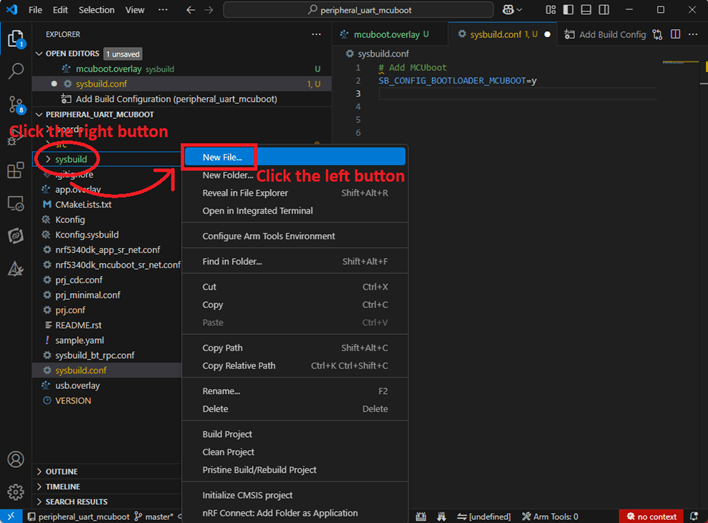
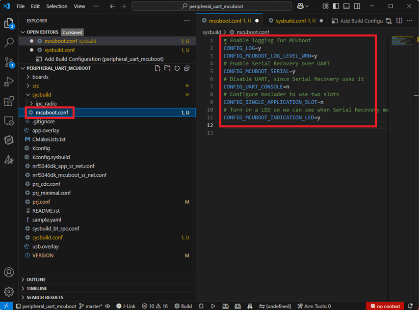
Step C1-1. Add build configuration to Board name: nrf52840dongle_nrf52840

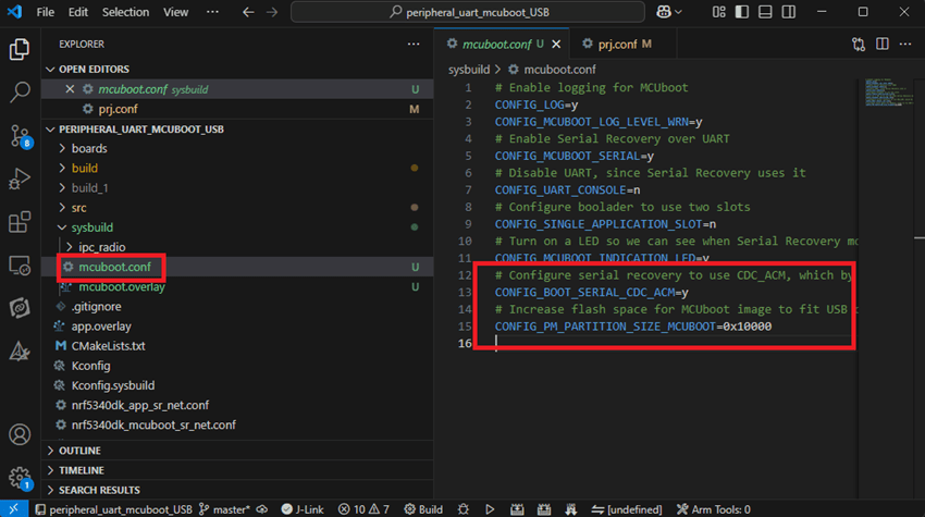
Step C1-2. Disable DCDC & DCDCHV by adding the below code into prj.conf file
CONFIG_BOARD_ENABLE_DCDC=n
CONFIG_BOARD_ENABLE_DCDC_HV=n

Step C1-3. Fix the VDD power to 3.0V or 3.3V in board.c file
The default power is 3.0V if you use board name: nrf52840dongle_nrf52840.
In this case, you don’t need to alter the power.

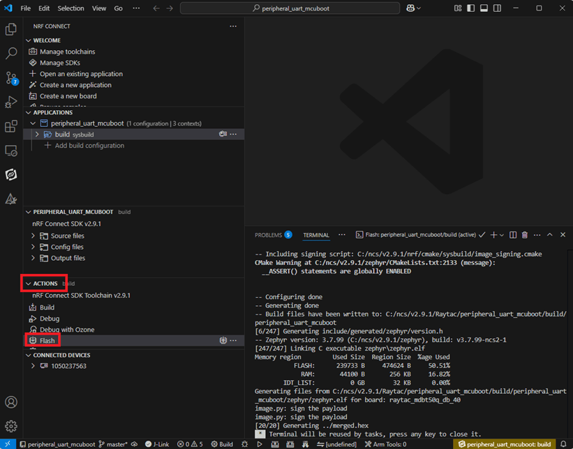
Step C1-4. Click the rebuild icon to reconfigure the program.

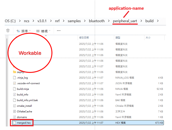
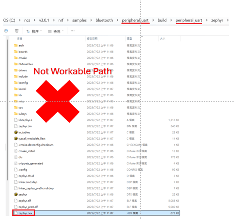
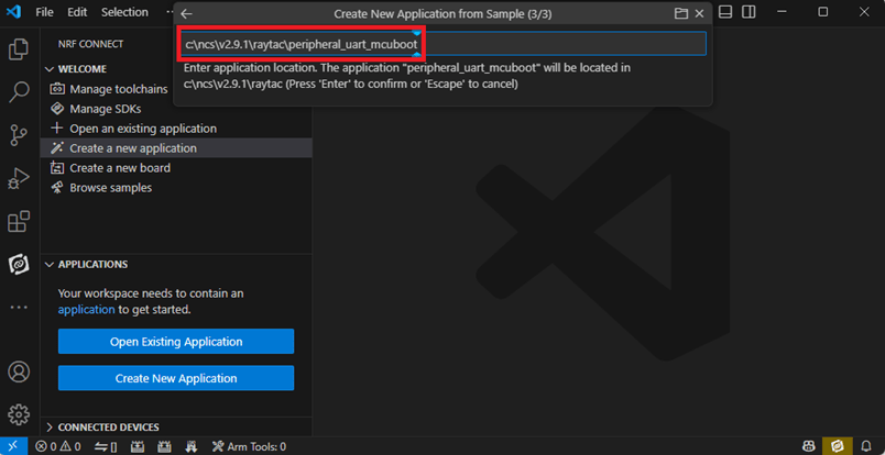
Step C1-5. The program will be saved automatically in the path below:
C:\ncs\v2.6.0\nrf\samples\bluetooth\peripheral_uart\build\zephyr\zephyr.hex
C2. nRF5 SDK:
Step C2-1. Open the program under:
\nRF5_SDK_17.1.0_ddde560\examples\peripheral\usbd_ble_uart\pca10056\s140\ses\ usbd_ble_uart_pca10056_s140.emProject
Step C2-2. Fix the VDD power supply to 3.0V or 3.3V.

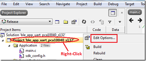
Step C2-3. Start editing the project by opening the solution in Editor.

Change the board name from PCA10056(nRF52840-DK) to PCA10059(nRF52840 dongle).
Save and re-compile the program after the amendment.

Click the program file name and save the modified project.

Press “Yes” to re-load the new set up value into configuration.

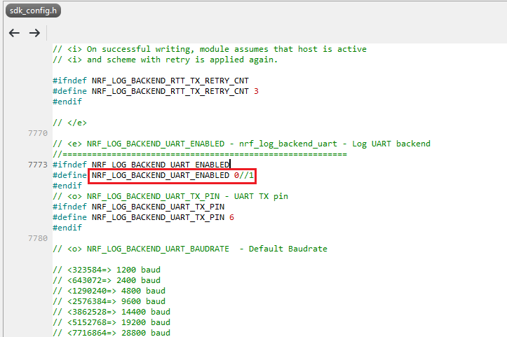
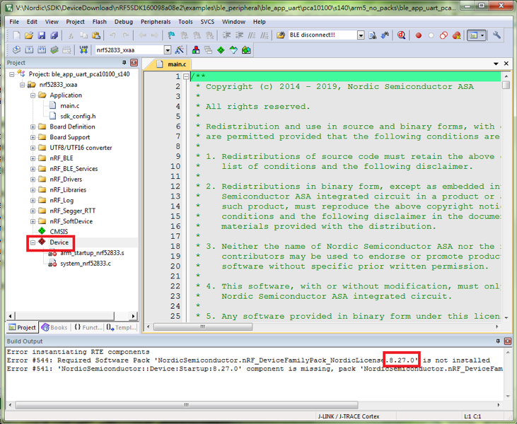
The default code in sdk_config.h is: NRF_LOG_BACKEND_UART_ENABLED 1 (in red frame);
Please change 1 to 0 to make the LED light work.
Press “Rebuild Solution” to make sure all the parameters you’ve modified are reconfigured.

Step C2-4. The program will be saved automatically under the path below:
V:\nRF5_SDK_17.1.0_ddde560\examples\ble_peripheral\ble_app_uart\pca10056\s140\ses\Output\Release\Exe\ble_app_uart_pca10056_s140.hex
D. Execute DFU (Device Firmware Update)
Reminder:
No extra bootloader can be programmed into MDBT50Q-CX until you manually wire the pins on the PCB and erase the built-in bootloader. You can simply operate DFU using MDBT50Q-CX’s bootloader.
Step D1. How to enable DFU?
(1) Press the button on MDBT50Q-CX
(2) Plug MDBT50Q-CX into your device while pressing the button
(3) Press and wait for approx.1 second until the LED light turns on. → DFU is activated.
(4) Release the button
※When Bootloader mode is enabled, the LED light on MDBT50Q-CX will twinkle continuously.

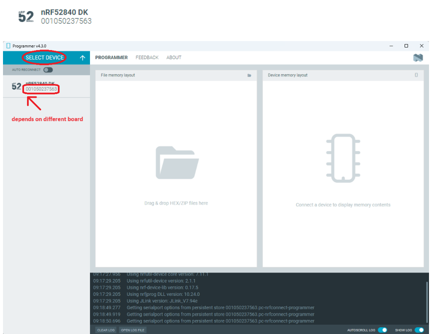
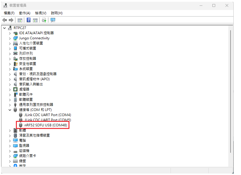
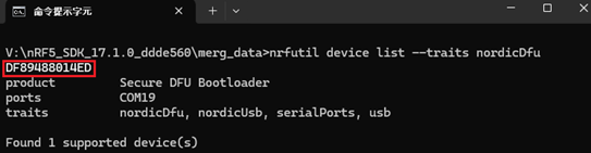
Step D2. Open the built-in DFU Bootloader
nRF Connect Desktop → Programmer → SELECT DEVICE → Open DFU Bootloader

You have successfully entered bootloader mode after you see the screen as below.

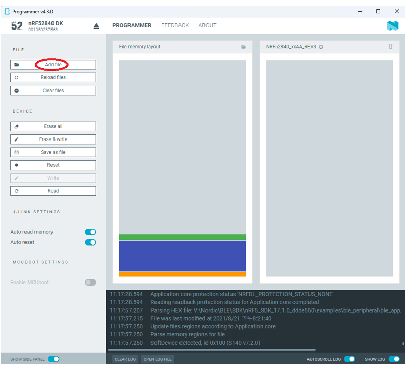
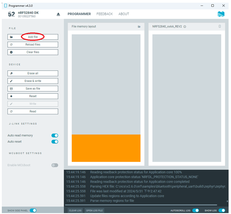
Step D3. Add ready firmware file into the Programmer
(The program completed and saved during Step C1-5(NCS) or Step C2-4(nRF5 SDK))
※If you’re using nRF5 SDK, you need to add the soft device file into your program for loading firmware.
※Soft device path:
nRF5_SDK_17.1.0_ddde560\components\softdevice\s140\hex\s140_nrf52_7.2.0_softdevice.hex

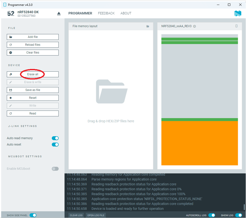
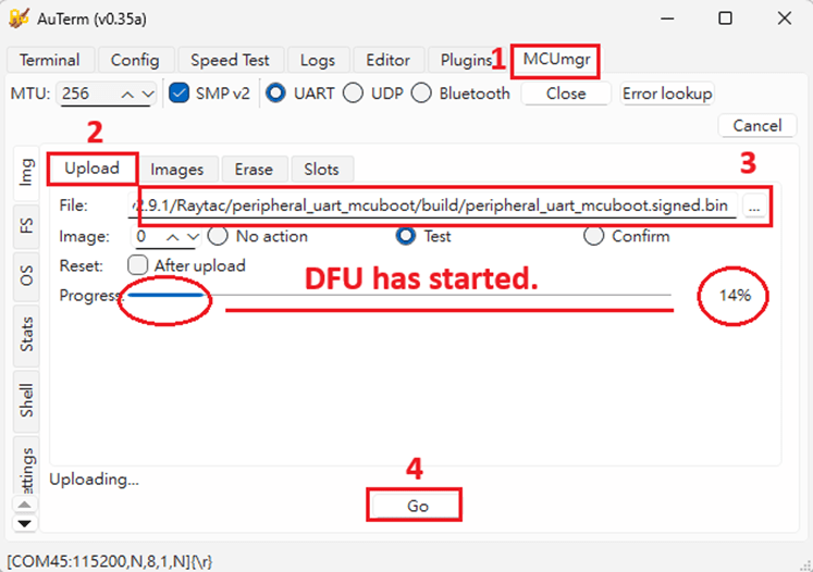
Step D4. Load the firmware and write it into the MDBT50Q-CX

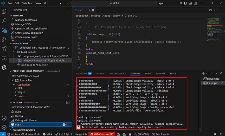
Step D5. Process FW DFU

Step D6. DFU Completed. The appointed firmware is successfully loaded into MDBT50Q-CX.

※Any failure during the DFU process will leave you under bootloader mode.

If this happens, simply restart the firmware writing process from Step D4 to reload your firmware into MDBT50Q-CX.
Edited by Sales Manager: Ms. Jocelyn Tsai
Technical guidance provided by Firmware Deputy Manager: Mr. Stanley Huang
Raytac Corporation 勁達國際電子股份有限公司
Bluetooth & WiFi & LoRa module maker based on Nordic nRF54, nRF53, nRF52, nRF7002 solution
BT5.4 &BT5.3 & BT5.2 & BT5.1 Qualified, FCC/IC/CE/Telec/KC/RCM/SRRC/NCC/WPC Pre-Certified.
Bluetooth Solution: nRF54, nRF5340, nRF52840, nRF52833, nRF52832, nRF52820, nRF52811, nRF52810, nRF52805, nRF51822
WiFi Solution: nRF7002
http://www.raytac.com
email: sales@raytac.com
Tel: +886-2-3234-0208


_1000X1000_190102")