There are no changes on Form, Fit, Function, and Quality of Reliability. Only change in u.FL Connector Appearance. All existing certifications and technical documentations remain valid.
We kindly invite our customers, distributors, and partners to update your records accordingly. For any questions or support regarding this update, feel free to reach out via: sales@raytac.com.
Raytac Corporation 勁達國際電子股份有限公司 / Raytac Corporation (USA) / abietec Inc. A Bluetooth, Wi-Fi, and LoRa Module Maker/ODM & OEM Manufacturer based on Nordic nRF54; nRF53: nRF52; nRF51; nRF7002 Semtech Specification: SX1262
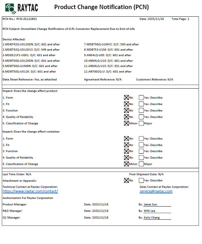
Raytac Corporation would like to inform all customers and partners of an official Product Change Notice: PCN-25100801 regarding the following product series:
Affected Series MDBT50Q-RX Series (nRF52840/833 based USB-A dongles)
Update of Raytac’s company logo on the nameplate, and
Addition of NCC logo on the back label.
There are no changes to product function, performance, quality, form factor, or safety compliances. All existing certifications and technical documentations remain valid.
We kindly invite our customers, distributors, and partners to update your records accordingly. For any questions or support regarding this update, feel free to reach out via: service@raytac.com.
Full details of the PCN please see below(Click on the images to zoom in). Remark: Please take note of the final shipment date.
Edited by Business Development Manager: Tony Yin
Raytac Corporation 勁達國際電子股份有限公司 / Raytac Corporation (USA) / abietec Inc. A Bluetooth, Wi-Fi, and LoRa Module Maker/ODM & OEM Manufacturer based on Nordic nRF54; nRF53: nRF52; nRF51; nRF7002 Semtech Specification: SX1262
In this article, Stanley Huang, MSc, Deputy Manager of Firmware Development at Raytac, shares insights on how Raytac’s modules and development kits strengthen the Zephyr ecosystem.
[Stanley Huang, New Taipei City] When we talk about open-source platforms like Zephyr RTOS, most people immediately think of major chip manufacturers such as ST Micro, NXP, or Nordic. But to me, what truly makes Zephyr famous amongst the developer community is through modules that developers can actually touch: those they can instantly plug in and start using right away. In these terms, Raytac is one of the most underrated and important contributors in this ecosystem.
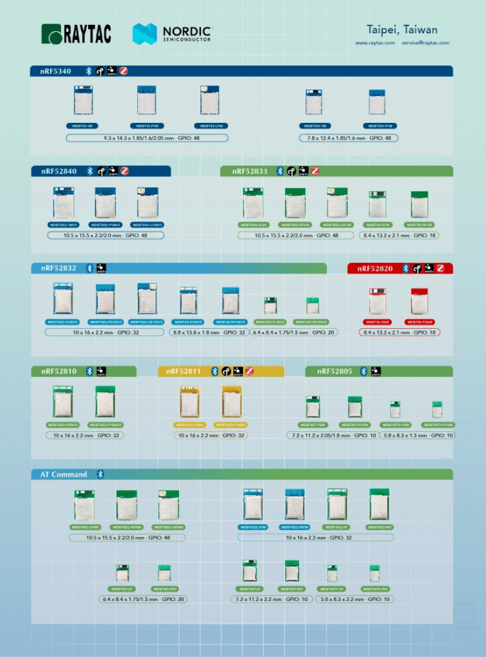
Raytac Modules Make Zephyr More Accessible Instead of being a chip vendor, we specialize in producing high-quality, globally certified modules – especially Bluetooth and Wi-Fi modules based on Nordic chipsets, such as the AN7002Q, AN54LQ, AN54LV, MDBT53, MDBT50Q, and MDBT42Q. All these modules are already certified with Regional RF compliances(FCC, IC, CE, KC, etc.) and the latest Bluetooth Specifications, offering developers the assurance of “plug and play” and “production-ready” solutions. We assure that our modules have become one of the easiest platforms for Zephyr developers to test BLE functionality.
I paired Zephyr with Raytac’s MDBT50Q-DB-40 development board when I first applied Zephyr in a BLE Peripheral project . With a simple west build -b nrf52840dk_nrf52840 followed by flashing the firmware using J-Link or nRF Connect for Desktop, the BLE beacon immediately showed up on my phone. Clean, simple, noise-free, and developer-friendly – that’s Raytac’s style.
Modules play an invaluable role in product development Many would say Raytac only makes modules and the real core is still Nordic’s SoC. But I believe that in an open-source system like Zephyr, the hardware that helps your project runs first is that which contributes the most. Our Zephyr-registered development kits eliminate the hassles of manual soldering, regulatory certification, and antenna design, allowing engineers to fully focus on developing applications based on Zephyr. They can run Zephyr’s BLE peripheral, central, GATT, and HCI samples directly on the Raytac kits that act as a one-stop hardware solution. In many ways, Raytac has pushed Zephyr’s usability a significant step forward.
Raytac Also Expands Zephyr’s Application Horizon Many of Raytac’s modules are ultra-compact- ideal for wearables, smart sensors, and low-power beacons…etc. These are the scenarios where Zephyr excels, and Raytac’s modules provide the physical platform to enable companies to build their “dream devices". When running Zephyr on a tiny module like the AN54LV-15(Product Link), developers will be amazed that something smaller than a piece of corn kernel can run a full RTOS, manage the BLE stack, trigger timers, drive I2C sensors, and even connect to the cloud, all by itself. This combination doesn’t just make development easier – it inspires developers to realize that: “they can build their projects using Raytac’s hardware.”
Raytac may not be the star, but we’re always ready for you On Zephyr’s main stage, companies like Nordic, STM, and Intel take the spotlight, but Raytac plays an essential supporting role – supporting the performance from behind the scenes. We offer stable, high quality, and low-power platforms, giving every line of Zephyr code a place to run and every feature a cornerstone. Our greatest value lies in helping developers skip antenna design and RF interference concerns – so they can jump right into the Zephyr ecosystem with ease.
Our products deliver the reliability you need and the efficiency you expect.
Zephyr RTOS hosted in Linux system has become a leading IoT ecosystem and it has been widely adopted as an open-source , real-time operation system for embedded devices, making it easier for developers to integrate the project smoothly.
Nordic Semiconductor , a main contributor to Zephyr, from the Bluetooth LE controller and USB stack to test tools, DFU frameworks.. and more, is making great effort and strategic decisions to adopt the Zephyr open-source into its nRFConnect(NCS) SDK program.
Raytac Corporation , a hardware-based manufacturer and a comprehensive solution developer with Nordic SoC development for multi-protocol complied wireless modules, now expands support for Zephyr RTOS ecosystem with its nRF52840 USB-C dongle – MDBT50Q-CX-40.
Reminder: The current Nordic released NCS SDK may NOT upgrade with Zephyr package at the same pace ; It is recommended to get the latest NCS SDK version to access the complete Zephyr support package.
If you’re interested in how Zephyr becomes powerful for a developer to start a project design easier and how the Nordic nRFConnect SDK community brings you to the world of Zephyr RTOS system, never hesitate to save the spot in the upcoming webinar on July 2nd, 2025. How Zephyr became the leading open-source RTOS for IoT(Click on the link to know more)
This guide teaches you how to use MCUboot for DFU (Device Firmware Update), Combined with nRF Connect SDK (NCS) V2.9.1 to upgrade firmware on Raytac’s MDBT50Q series modules.
Table of contents:
Hardware Set Up
Software Kits resource download & install
Compile and load the program a. Open VS Code b. Project setup c. Setup the situation for DFU over UART or DFU over USB d. Start compiling your project e. Load your compiled program into the MDBT50Q-DB-40 demo board
Install nRF Connect for Desktop ➔ install Programmer and Toolchain Manager.
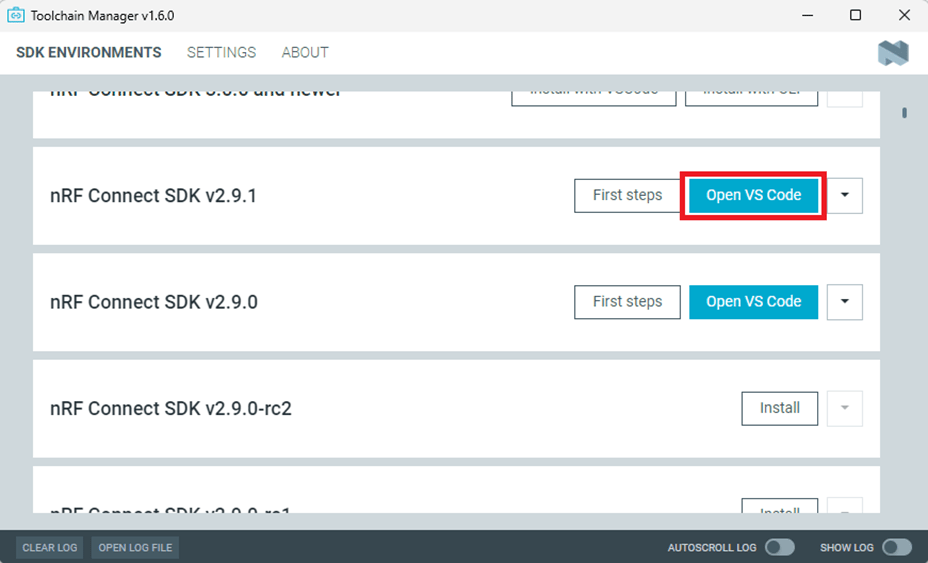
Open Toolchain Manager and install SDK V2.9.1.
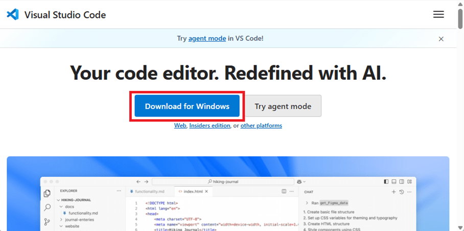
Install Visual Studio Code
3. Compile and load the program a. Open VS Code(Visual Studio Code)
Note: If it’s your first time using the software: after installing all the extensions, you should see the same on your screen.
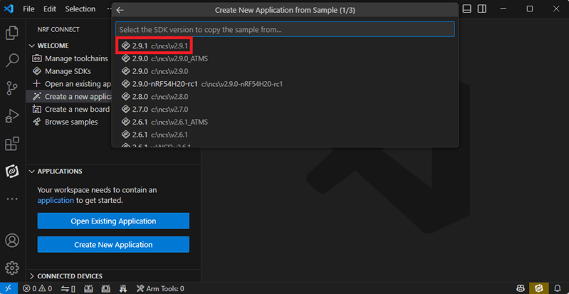
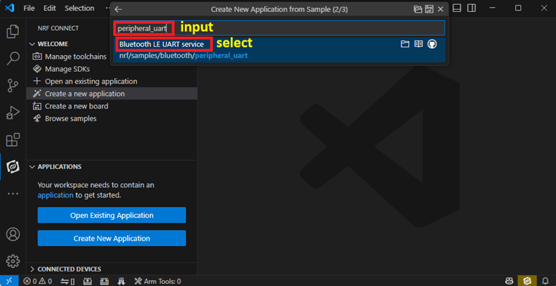
b. Project setup b.1 Create an example code(In this article: peripheral_uart) Please refer to the following steps: Create a new application ➔ Copy a sample ➔ NCS V2.9.1
b.2 Name the Project: peripheral_uart Input peripheral_uart and the corresponding example program will appear in the options section below.
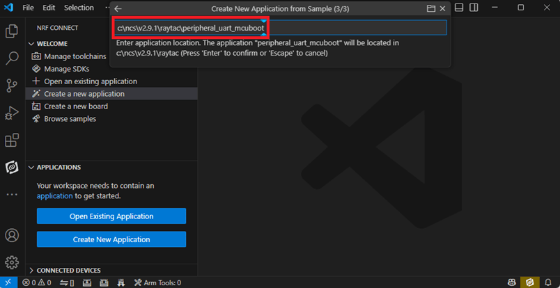
Note: We named the project peripheral_uart_mcuboot to distinguish it. This project will create a directory named peripheral_uart_mcuboot.
c.Build an environment for DFU over UART or DFU over USB – Create a new application ➔ Open
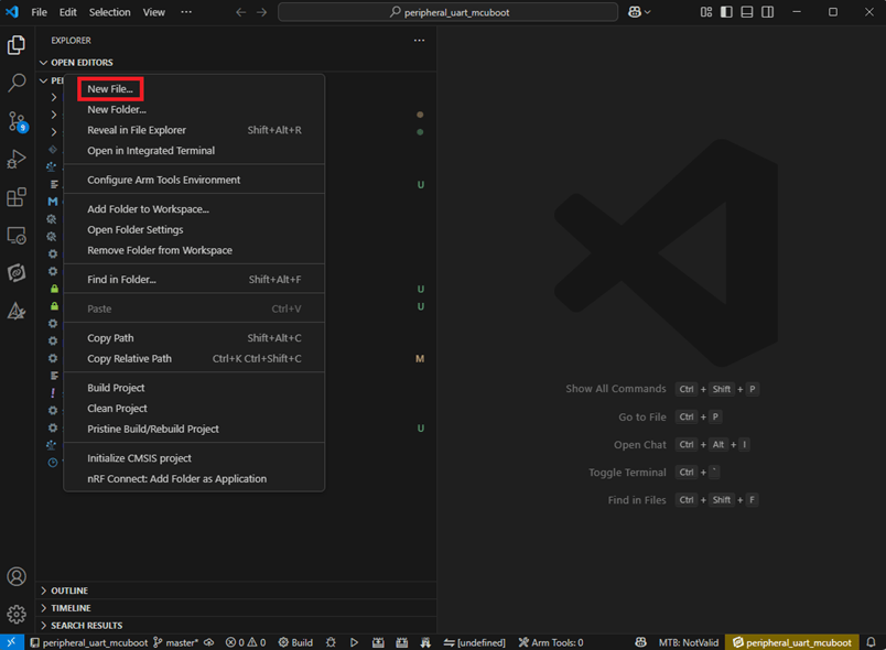
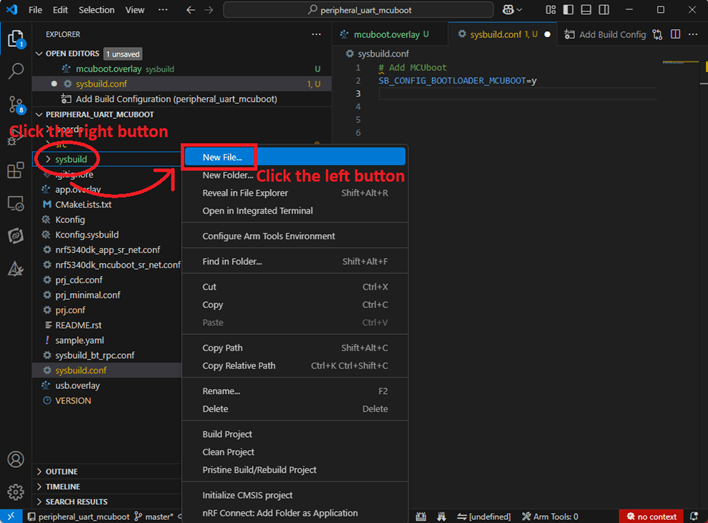
Right click on the project name you just created (peripheral_uart_mcuboot), a pop-up menu will appear. Select the first option “Show in Explorer" from the pop-up menu to display all project files.
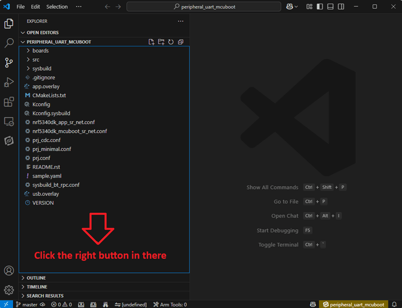
Then select New File to create a sysbuild.conf file.
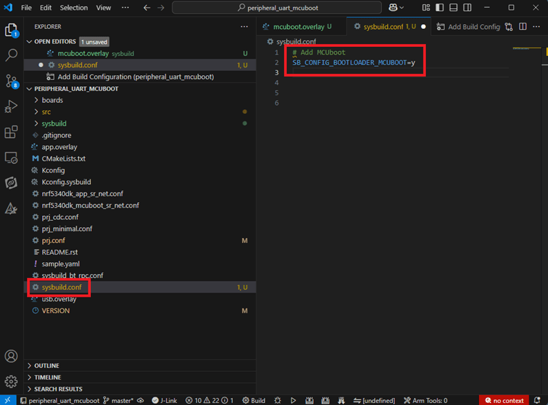
select sysbuild.conf, left-click on it, and a blank box will show.
Input the file name and write: SB_CONFIG_BOOTLOADER_MCUBOOT=y
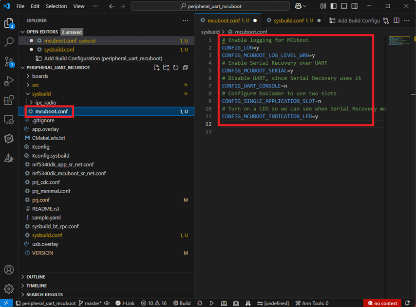
Parameters and instructions Add a new file mcuboot.conf, in the sysbuild folder, and input the following parameters into the file. (Add relevant parameters according to UART or USB) (Note: Please be informed if you want to use DFU over UART in the end, you should use UART when you first create the environment. Similarly, if you want to use DFU over USB, you should create the USB environment at the beginning.)
For DFU over UART # Enable logging for MCUboot CONFIG_LOG=y CONFIG_MCUBOOT_LOG_LEVEL_WRN=y # Enable Serial Recovery over UART CONFIG_MCUBOOT_SERIAL=y # Disable UART, since Serial Recovery uses it CONFIG_UART_CONSOLE=n # Configure the bootloader to use two slots CONFIG_SINGLE_APPLICATION_SLOT=n # Turn on a LED so we can see when Serial Recovery mode is active CONFIG_MCUBOOT_INDICATION_LED=y
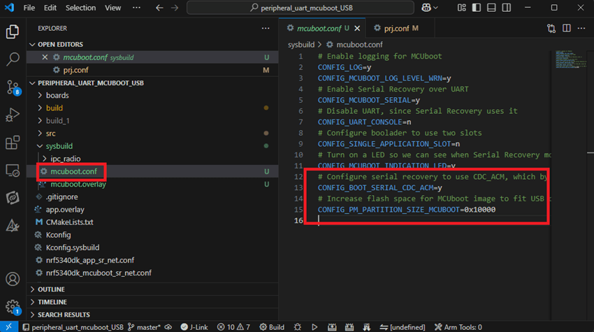
For DFU over USB # Enable logging for MCUboot CONFIG_LOG=y CONFIG_MCUBOOT_LOG_LEVEL_WRN=y # Enable Serial Recovery over UART CONFIG_MCUBOOT_SERIAL=y # Disable UART, since Serial Recovery uses it CONFIG_UART_CONSOLE=n # Configure bootloader to use two slots CONFIG_SINGLE_APPLICATION_SLOT=n # Turn on a LED so we can see when Serial Recovery mode is active CONFIG_MCUBOOT_INDICATION_LED=y # Configure serial recovery to use CDC_ACM, which by default uses the USB CONFIG_BOOT_SERIAL_CDC_ACM=y # Increase flash space for the MCUboot image to fit USB drivers CONFIG_PM_PARTITION_SIZE_MCUBOOT=0x10000
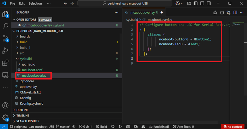
Create a new file: mcuboot.overlay and add the following parameters.
For DFU over UART /* Configure button and LED for Serial Recovery */ / { aliases { mcuboot-button0 = &button0; mcuboot-led0 = &led0; }; };
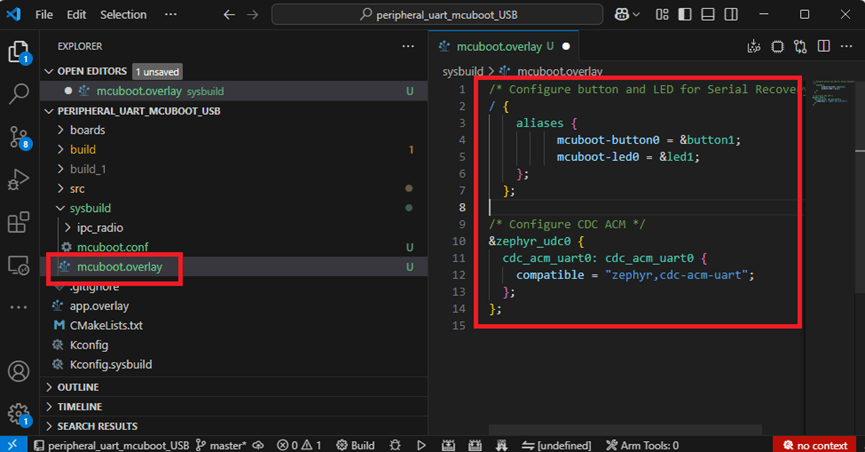
For DFU over USB /* Configure button and LED for Serial Recovery */ / { aliases { mcuboot-button0 = &button0; mcuboot-led0 = &led0; }; }; /* Configure CDC ACM */ &zephyr_udc0 { cdc_acm_uart0: cdc_acm_uart0 { compatible = “zephyr,cdc-acm-uart"; }; };
Note: if you use DFU over USB, please enable the USB subsystem in prj.conf.
After all the setup is completed, you can start compiling your project.
d. Start compiling your project Add Build Configuration ➔ Select target board ➔ In this example, choose raytac_mdbt50q_db_40/nrf52840.
Start compiling by clicking “Generate and Build" at the bottom-right corner.
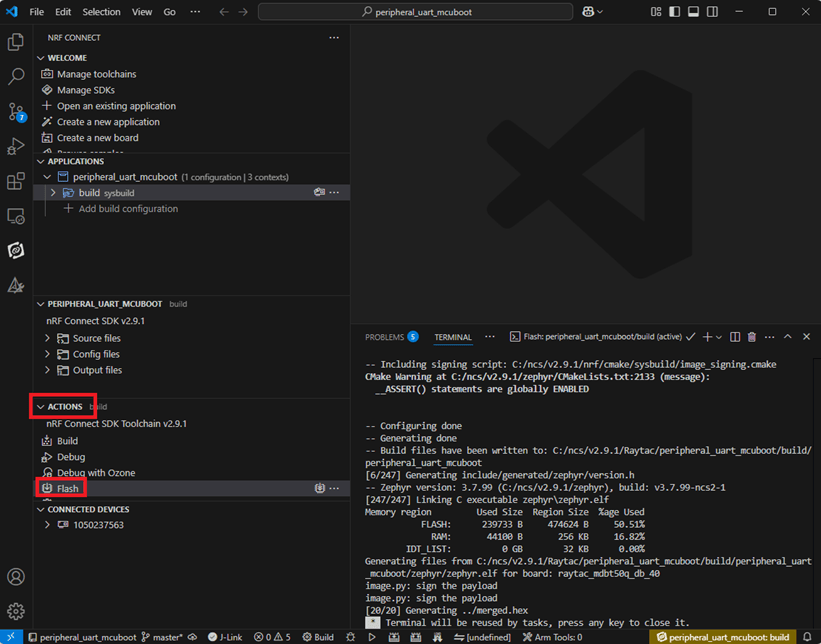
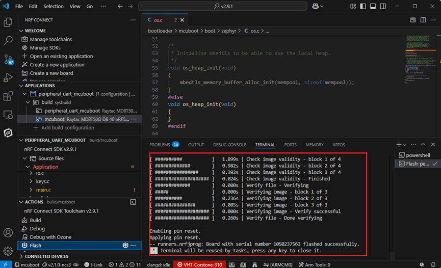
e. Load your compiled program into the MDBT50Q-DB-40 demo board After compiling without error, select the flash function to load your program into the MDBT50Q-DB-40 demo board.
If the below is shown, it means that you have successfully loaded your program into the demo board.
4. DFU to MDBT50Q-DB-40 through UART / USB DFU over UART Hold the SW2 button then plug the power into the USB connector. The system will enter the bootloader mode. You can then DFU the new firmware via the UART.
DFU over USB If you update your firmware through USB, please also hold the SW2 button and connect the USB cable.
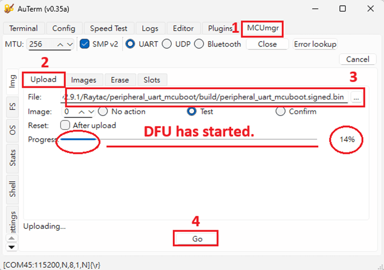
Steps: Select the tab Config to set the correct COM port.
Follow the sequences in the below screenshot.
You can use the file peripheral_uart_mcuboot.signed.bin for testing. It is located in peripheral_uart_mcuboot/build. Then follow the sequences in the below screenshot. DFU will be completed when the progress reaches 100%.
6. DFU using your custom keys When you compile the code, you will see the below warning. Reason: It’s required to have your own private key to ensure your product’s security. Following are the steps to enable security features.
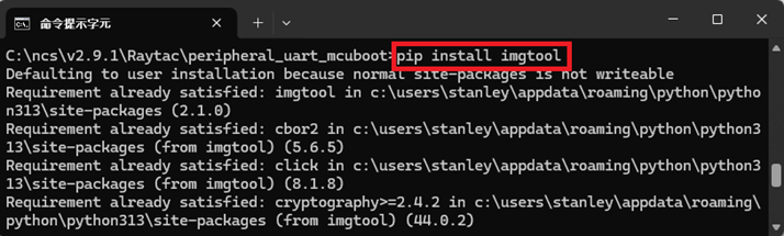
Step 1. Create the key First, install the imgtool program using pip.
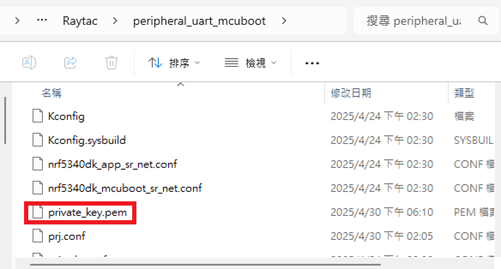
Then use the following command to generate your private key in your project folder. After the private key is generated, you can access it in your directory.
Step 2. Configure the project to use this key in sysbuild.conf
# Add MCUboot SB_CONFIG_BOOTLOADER_MCUBOOT=y #Add private key for MCUboot SB_CONFIG_BOOT_SIGNATURE_KEY_FILE="\${APP_DIR}/private_key.pem" # Configure key type SB_CONFIG_BOOT_SIGNATURE_TYPE_ECDSA_P256=y
Step 3. Build and flash the project again. Your firmware will have security features.
Edited by Account Manager: Mr. Welson Kuo
Raytac Corporation 勁達國際電子股份有限公司 / Raytac Corporation (USA) A Bluetooth, Wi-Fi, and LoRa Module Maker/ODM & OEM Manufacturer based on Nordic nRF54; nRF53: nRF52; nRF51; nRF7002 Semtech Specification: SX1262
By obtaining wireless (Bluetooth) certification, manufacturers can demonstrate that their products comply with the required technical reliability. In another words, these certifications are like products’ passes, allow them legally entering the market and be able to import or export specific countries. Modular approval and Non-modular approval are two different approaches to the certification and regulatory processes for wireless communication devices.
Modular approval is a process in which a wireless device is certified as a modular component, such as a Bluetooth module, that can be integrated into multiple host devices without additional testing for each host device. Once certified, the module can be used in various host devices without undergo the same level of testing.
Non-modular approval is also known as end-product approval, is the traditional certification process for wireless devices, where the entire device needs to be tested and certified for compliance with wireless (Bluetooth) standards and regulations.
Countries follow and under modular approval such as FCC (USA), IC (Canada), Telec (Japan), KC (South Korea), NCC(Taiwan), SRRC(China)…etc.Meanwhile, countries are under non-modular approval, we have CE (Europe), RCM (Australia and New Zealand)…etc.
The elaboration and the easy steps on how the process we go through as you choose Raytac, detail for each as following:
Modular Approval:
FCC (USA) FCC ID Search | Federal Communications Commission 1. Part 15C –> Simply use our module FCC ID on product label 2. Part 15B (EMC) –> request lab to test on EMC, SDoc* *Definition: SDoc(Supplier’s Declaration of conformity) One way to show that a product, process or service to comply with a standard or technical regulation, in which a supplier provides written assurance of conformity to the specified requirements.
IC (Canada) IndustryCanda Wireless ID Database (industrycanada.co) 1.Similar to FCC –> Simply use our module IC ID on product label. 2.–> request lab to test finished good on EMC (IC ES003). Recommend combining test with FCC Part 15B
Telec (MIC)(Japan) MIC ICT Policy (soumu.go.jp) 1.–> Simply use our module Telec ID on product label 2.Different from the USA and Canada –> EMC is optional in Japan, upon on end customer’s request.
KC (South Korea) South Korea – Labeling/Marking Requirements (trade.gov) 1. Wireless test can be continued to use module report, new test is not required. 2. EMC KN301489(same rule as CE EN301489) –> to be tested based on final goods under EMC test policy. Same rules as FCC and IC. Recommend combining test with FCC Part 15B. 3. If product obtain additional cable IO port, test on KN3235 is required. 4. To be KC certified, the new test is required, certification no. cannot be continued to use from other policy. And the test must be done locally.
NCC (Taiwan) NATIONAL COMMUNICATIONS COMMISSION (ncc.gov.tw) 1. Products is compliant with platform policy –> lab submit photo and add product under Raytac NCC no. 2. Products is not compliant with platform policy –> product must be tested as final goods at the lab to be certified. *Definition: platform policy: product itself has it’s own function before Bluetooth was installed. For example, a Bluetooth installed pen has a new function; it vibrates when the switch is on. In this scenario, pen originally has it’s own function, and now the addition function; vibration has been added to this device. We say this product is compliant with platform policy.
SRRC (China) State Radio Regulation of China (srrc.org.cn) 1. –>Simply use our module SRRC ID on product label. 2. Products doesn’t under the category of home electronics / office supplies, SRRC test must be implemented.
Non-Modular Approval:
CE (Europe) CE Marking (trade.gov) 1. Wireless test: EN300328 –> Conducted test could continue to use Raytac ‘s CE report. –> Radiated test is required to be tested based on final goods under wireless regulation. 2. EN301489 (EMC) –> Same rules as FCC and IC. Recommend combining test with FCC Part 15B 3. Safety test: EN60950 (EN62368)–> safety test is required to be tested based on final goods under regulation.
RCM (Australia and New Zealand) The Regulatory Compliance Mark (RCM) (General) – EESS 1. Products is CE certified –>lab can copy CE report to apply RCM 2. Products is not CE certified –> go through the same test as CE regulations.
Overall, it’s important to note that the certification process and requirements may vary across different regions. Manufacturers should consult the relevant certification authorities to determine the specific requirements for their wireless devices. Raytac already took a step ahead gone through complex procedures of obtaining certifications, and we also have strong IT team to support for best solutions.Choosing Raytac would allow you to work more efficient and it will be your key in success for all the projects.
Edited by Sales Manager: Mandy Chao
Raytac Corporation 勁達國際電子有限公司 A Bluetooth & WiFi module maker based on Nordic nRF54, nRF53, nRF52, nRF7002 solution www.raytac.com email: service@raytac.com Tel: +886.2.3234.0208
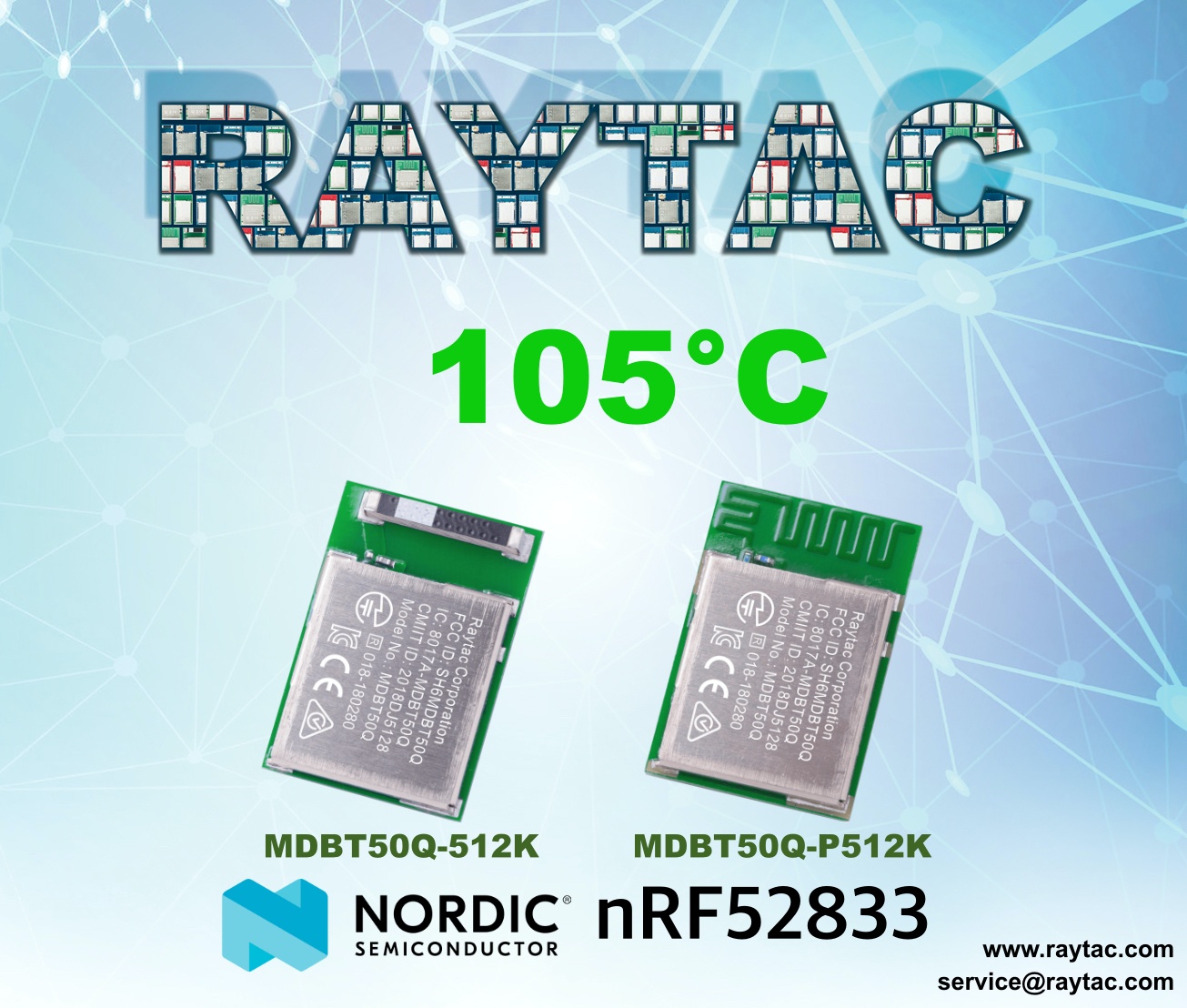
Raytac announced both MDBT50Q-512K & MDBT50Q-P1M modules has extended the ambient temperature up to 105°C, following Nordic’s nRF52833’s specification.
nRF52833 Module MDBT50Q By Raytac Has Extended To 105°C Ambient Temperature
Unlike a single component like SoC, modules acted as an integrated equipment which includes some other related components. To secure the module works under the latest environment request while Nordic nRF52833 released, Raytac ensured all related components meet the new temperature requirement with RF efficiency secured.
Today, we are pleased to announce nRF52833 modules:
MDBT50Q-512K: Chip Antenna
MDBT50Q-P512K: PCB Antenna
Both have successfully extended ambient temperature to 105°C which are the most ideal devices for a wide range of commercial and industrial applications.
Raytac Corporation 勁達國際電子有限公司
A BT5.2 & BT5.1 & BT5 & BT 4.2 module maker based on Nordic nRF52 & nRF51 solution
Just right at the start of 2020, we are happy to announce nRF52833 modules are now available!
Raytac’s nRF52833 series modules are introduced in 3 kinds of antenna options (Chip Ceramic / PCB / u.FL connector for external antenna) brings the best usability to meet different implements.
Developer who currently are using nRF52840 based modules must be excited waiting for nRF52833’s distribution. Most developers are aware that nRF52833 supports long range, multi protocol and USB interface but has less RAM and Flash memory rather than nRF52840 and no doubt is the best alternative to have cost effective without extra efforts.
Raytac has released 3 models of nRF52833 based modules just at the same time when Nordic released, MDBT50Q-512K / MDBT50Q-P512K / MDBT50Q-U512K. Both nRF52840 and nRF52833 module are based on same form factor and pin out. To have quick visual identification finding the difference, Raytac’s nRF52833 modules are built by Green PCB but nRF52840 modules are Blue.