Raytac’s Impact on the Zephyr Ecosystem – Little Module, Huge Potential

In this article, Stanley Huang, MSc, Deputy Manager of Firmware Development at Raytac, shares insights on how Raytac’s modules and development kits strengthen the Zephyr ecosystem.

[Stanley Huang, New Taipei City]
When we talk about open-source platforms like Zephyr RTOS, most people immediately think of major chip manufacturers such as ST Micro, NXP, or Nordic. But to me, what truly makes Zephyr famous amongst the developer community is through modules that developers can actually touch: those they can instantly plug in and start using right away. In these terms, Raytac is one of the most underrated and important contributors in this ecosystem.

Raytac Modules Make Zephyr More Accessible
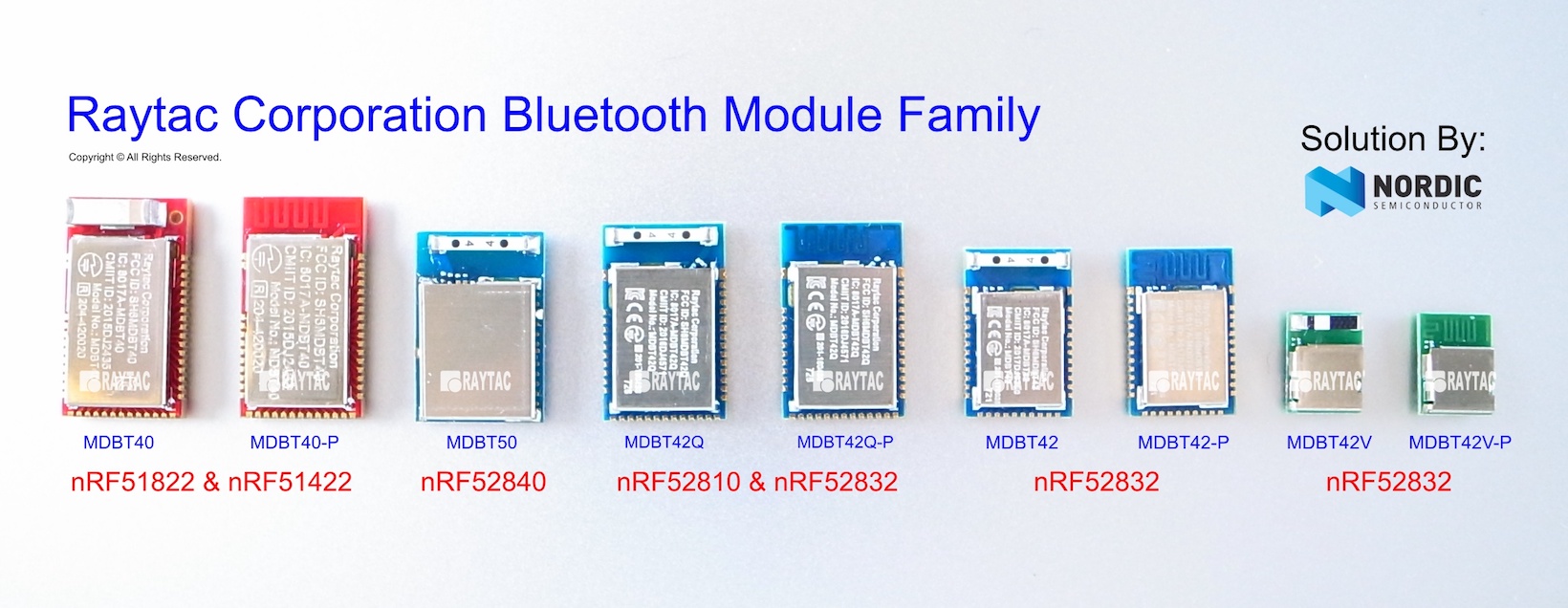
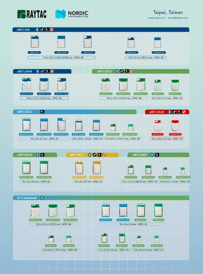
Instead of being a chip vendor, we specialize in producing high-quality, globally certified modules – especially Bluetooth and Wi-Fi modules based on Nordic chipsets, such as the AN7002Q, AN54LQ, AN54LV, MDBT53, MDBT50Q, and MDBT42Q.
All these modules are already certified with Regional RF compliances(FCC, IC, CE, KC, etc.) and the latest Bluetooth Specifications, offering developers the assurance of “plug and play” and “production-ready” solutions.
We assure that our modules have become one of the easiest platforms for Zephyr developers to test BLE functionality.

I paired Zephyr with Raytac’s MDBT50Q-DB-40 development board when I first applied Zephyr in a BLE Peripheral project . With a simple west build -b nrf52840dk_nrf52840 followed by flashing the firmware using J-Link or nRF Connect for Desktop, the BLE beacon immediately showed up on my phone. Clean, simple, noise-free, and developer-friendly – that’s Raytac’s style.

Modules play an invaluable role in product development
Many would say Raytac only makes modules and the real core is still Nordic’s SoC.
But I believe that in an open-source system like Zephyr, the hardware that helps your project runs first is that which contributes the most.
Our Zephyr-registered development kits eliminate the hassles of manual soldering, regulatory certification, and antenna design, allowing engineers to fully focus on developing applications based on Zephyr.
They can run Zephyr’s BLE peripheral, central, GATT, and HCI samples directly on the Raytac kits that act as a one-stop hardware solution.
In many ways, Raytac has pushed Zephyr’s usability a significant step forward.

Raytac Also Expands Zephyr’s Application Horizon
Many of Raytac’s modules are ultra-compact- ideal for wearables, smart sensors, and low-power beacons…etc. These are the scenarios where Zephyr excels, and Raytac’s modules provide the physical platform to enable companies to build their “dream devices".
When running Zephyr on a tiny module like the AN54LV-15(Product Link), developers will be amazed that something smaller than a piece of corn kernel can run a full RTOS, manage the BLE stack, trigger timers, drive I2C sensors, and even connect to the cloud, all by itself.  This combination doesn’t just make development easier – it inspires developers to realize that: “they can build their projects using Raytac’s hardware.”

Raytac may not be the star, but we’re always ready for you
On Zephyr’s main stage, companies like Nordic, STM, and Intel take the spotlight, but Raytac plays an essential supporting role – supporting the performance from behind the scenes. We offer stable, high quality, and low-power platforms, giving every line of Zephyr code a place to run and every feature a cornerstone.
Our greatest value lies in helping developers skip antenna design and RF interference concerns – so they can jump right into the Zephyr ecosystem with ease.

Our products deliver the reliability you need and the efficiency you expect.

We invite you to explore more about how Raytac supports the Zephyr ecosystem and discover our range of development kits and modules designed for seamless integration.
Visit our Zephyr page here: https://docs.zephyrproject.org/latest/boards/raytac/index.html
Visit Zephyr’s Ecosystem Vendors page: https://www.zephyrproject.org/ecosystem-vendor-offerings/

For more information, please contact:
Raytac Contact Form: https://www.raytac.com/contact/
Raytac Sales email: sales@raytac.com
abietec Service email: service@abietec.com


Article by Firmware Deputy Manager: Stanley Huang
Edited by Business Development Manager: Tony Yin

Raytac Corporation 勁達國際電子股份有限公司 / Raytac Corporation (USA) / abietec Inc.
A Bluetooth, Wi-Fi, and LoRa Module Maker/ODM & OEM Manufacturer based on
Nordic nRF54; nRF53: nRF52; nRF51; nRF7002
Semtech Specification: SX1262

Bluetooth Specification: BT6 ; BT5.4 ; BT5.3 ; BT5.2.
Wi-Fi Specification: Wi-Fi 6
LoRa Specification: LoRaWAN


All products are FCC/IC/CE/Telec/KC/RCM/SRRC/NCC/WPC/RoHS/Reach Pre-Certified.
http://www.raytac.com
https://www.raytac.com/contact/
email: sales@raytac.com
Tel: +886-2-3234-0208(TW)/+1-626-217-3139(USA)

Essential Tips for nRF54L15 HEX File Verification

Hi readers, did you know that Raytac offers a special service exclusively for our customers? 😉
We offer support services: HEX file verification and flashing firmware into modules per customer’s requests.
Compared to the series nRF52 and nRF53’s 2 in 1 or 3 in 1 merged hex files, nRF54L15 requires something slightly different. Following are the tips and suggestions.

Before building your own .hex file on Raytac’s nRF54L15 modules(Product link), please configure some settings(shown below) in advance.

In VS Code:

  1. Go to Add Build Configuration
  2. Find System Build (sysbuild) ➝ Choose Build System Default
  3. Click Generate and Build


Starting from NCS v2.8.0 (including later versions), the .hex file can be generated in two different paths.
1. ..\nrf\samples\bluetooth\application-name\build\merged.hex
2. ..\nrf\samples\bluetooth\application-name\build\application-name\zephyr\zephyr.hex


Using the AN54LQ/AN54LV series as an example:
When you provide the programming file (.hex) for production, please ensure that the file is taken from the following path:
1. ..\nrf\samples\bluetooth\application-name\build\merged.hex
And we also do not recommend renaming the merged HEX file due to Nordic suggestions.

For more details behind this suggestion, please refer to the Nordic DevZone link below.
https://devzone.nordicsemi.com/f/nordic-q-a/120313/how-to-modify-the-name-of-the-merged-hex-file


Suggested path:
1. ..\nrf\samples\bluetooth\application-name\build\merged.hex

Not recommended path:
2. ..\nrf\samples\bluetooth\application-name\build\application-name\zephyr\zephyr.hex
The zephyr.hex file is not recommended to be used for flashing or verification in the production process.

Thank you all for your patience in reading!
Best wishes for your projects – your success is Raytac’s success! 😊


For more information, please contact:
Raytac Contact Form: https://www.raytac.com/contact/
Raytac Sales email: sales@raytac.com
abietec Service email: service@abietec.com


Edited by Account Manager: Ms. Elfreda Guo


Raytac Corporation 勁達國際電子股份有限公司 / Raytac Corporation (USA) / abietec Inc.
A Bluetooth, Wi-Fi, and LoRa Module Maker/ODM & OEM Manufacturer based on
Nordic nRF54; nRF53: nRF52; nRF51; nRF7002
Semtech Specification: SX1262


Bluetooth Specification: BT6 ; BT5.4 ; BT5.3 ; BT5.2.
Wi-Fi Specification: Wi-Fi 6
LoRa Specification: LoRaWAN


All products are FCC/IC/CE/Telec/KC/RCM/SRRC/NCC/WPC/RoHS/Reach Pre-Certified.
http://www.raytac.com
https://www.raytac.com/contact/
email: sales@raytac.com
Tel: +886-2-3234-0208(TW)/+1-626-217-3139(USA)

Understanding Wireless Certification and Compliance:A Guide to Module and Non-Module Approval Processes

Certification and compliance:

By obtaining wireless (Bluetooth) certification, manufacturers can demonstrate that their products comply with the required technical reliability. In another words, these certifications are like products’ passes, allow them legally entering the market and be able to import or export specific countries. Modular approval and Non-modular approval are two different approaches to the certification and regulatory processes for wireless communication devices.

Modular approval is a process in which a wireless device is certified as a modular component, such as a Bluetooth module, that can be integrated into multiple host devices without additional testing for each host device. Once certified, the module can be used in various host devices without undergo the same level of testing.

Non-modular approval is also known as end-product approval, is the traditional certification process for wireless devices, where the entire device needs to be tested and certified for compliance with wireless (Bluetooth) standards and regulations.

Countries follow and under modular approval such as FCC (USA), IC (Canada), Telec (Japan), KC (South Korea), NCC(Taiwan), SRRC(China)…etc.Meanwhile, countries are under non-modular approval, we have CE (Europe), RCM (Australia and New Zealand)…etc.

The elaboration and the easy steps on how the process we go through as you choose Raytac, detail for each as following:

Modular Approval:

FCC  (USA)
FCC ID Search | Federal Communications Commission
1. Part 15C –> Simply use our module FCC ID on product label
2. Part 15B (EMC) –> request lab to test on EMC, SDoc*
*Definition: SDoc(Supplier’s Declaration of conformity)
One way to show that a product, process or service to comply with a standard or technical regulation, in which a supplier provides written assurance of conformity to the specified requirements.

IC (Canada)
IndustryCanda Wireless ID Database (industrycanada.co)
1.Similar to FCC –> Simply use our module IC ID on product label.
2.–> request lab to test finished good on EMC (IC ES003).
Recommend combining test with FCC Part 15B

Telec (MIC)(Japan)
MIC ICT Policy (soumu.go.jp)
1.–> Simply use our module Telec ID on product label
2.Different from the USA and Canada –> EMC is optional in Japan, upon on end customer’s request.

KC  (South Korea)
South Korea – Labeling/Marking Requirements (trade.gov)
1. Wireless test can be continued to use module report, new test is not required.
2. EMC KN301489(same rule as CE EN301489)
–> to be tested based on final goods under EMC test policy. Same rules as FCC and IC.
Recommend combining test with FCC Part 15B.
3. If product obtain additional cable IO port, test on KN3235 is required.
4. To be KC certified, the new test is required, certification no. cannot be continued to use from other policy. And the test must be done locally.

NCC (Taiwan)
NATIONAL COMMUNICATIONS COMMISSION (ncc.gov.tw)
1. Products is compliant with platform policy –> lab submit photo and add product under Raytac NCC no.
2. Products is not compliant with platform policy –> product must be tested as final goods at the lab to be certified.
*Definition: platform policy: product itself has it’s own function before Bluetooth was installed. For example, a Bluetooth installed pen has a new function; it vibrates when the switch is on. In this scenario, pen originally has it’s own function, and now the addition function; vibration has been added to this device. We say this product is compliant with platform policy.

SRRC (China)
State Radio Regulation of China (srrc.org.cn)
1. –>Simply use our module SRRC ID on product label.
2. Products doesn’t under the category of home electronics / office supplies, SRRC test must be implemented.

Non-Modular Approval:

CE  (Europe)
CE Marking (trade.gov)
1. Wireless test: EN300328
–> Conducted test could continue to use Raytac ‘s CE report.
–> Radiated test is required to be tested based on final goods under wireless regulation.
2. EN301489 (EMC) –> Same rules as FCC and IC. Recommend combining test with FCC Part 15B
3. Safety test: EN60950 (EN62368)–> safety test is required to be tested based on final goods under regulation.

RCM (Australia and New Zealand)
The Regulatory Compliance Mark (RCM) (General) – EESS
1. Products is CE certified –>lab can copy CE report to apply RCM
2. Products is not CE certified –> go through the same test as CE regulations.

Overall, it’s important to note that the certification process and requirements may vary across different regions. Manufacturers should consult the relevant certification authorities to determine the specific requirements for their wireless devices.
Raytac already took a step ahead gone through complex procedures of obtaining certifications, and we also have strong IT team to support for best solutions.Choosing Raytac would allow you to work more efficient and it will be your key in success for all the projects.

Edited by Sales Manager: Mandy Chao

Raytac Corporation 勁達國際電子有限公司
A Bluetooth & WiFi module maker based on Nordic nRF54, nRF53, nRF52, nRF7002 solution 
www.raytac.com email: service@raytac.com Tel: +886.2.3234.0208           


Regulations, Certifications and Raytac’s Modules – What do we make more convenient for our customers?

Raytac’s pre-certified module for your convenience – but how?So, in this post, we would like to take you on a little journey through most of the important certifications that Raytac has pre-certified their modules with.
The exact topic is actually what you need to know and what that means to you as a Raytac customer.Obviously, each and every certification has their own rules, so that’s how we’re going to do this – one by one.

  1. FCC – (U.S.A.)

Most people in the industry have heard of FCC, but for you who really don’t know what it is, it’s the Federal Communications Commission in the United States of America. Although considered as a center for these regulations, you will soon realize that they’re not really the center of these regulations and laws at all.
So for the FCC certification, you can as a Raytac customer:

    1. Use Raytac’s certification ID directly on your finished product’s label

But you need to:

  1. Test FCC Part 15B EMC for your finished products
  1. IC – (Canada)

When it comes to the Industry Canada (yes, that’s what IC stands for), the regulations and procedures are much like their sibling FCC.

    1. Use Raytac’s certification ID on your finished product’s label (same as FCC)

But, just like FCC, you need to:

  1. Test IC ES003 (EMC)
    • This can be combined together with the FCC Part 15B test
  1. TELEC – (Japan)

TELEC, sometimes referred to as MIC, is surprisingly simple.
What you will need to do is:

  1. Use Raytac’s certification ID on your finished product’s label

Yes – you can actually just go right ahead and implement and/or commercialize your product after its parts are all proven TELEC certified which is pretty neat. However, there is another test that you as a customer can do if you wish, and that is VCCI which is just like the EMC tests mentioned above with the only difference (in terms of regulation) is that it’s NOT mandatory. Thus, you can choose not to do it as well.

  1. KC – (South Korea)

As for the Korean regulation, these are the things you will have to do:

  1. Test EMC for wireless (KN301489 – same as CE’s EN301489)
  2. Test EMC for wire (IO port) (KN3235)
    • If, and only if, your final product is equipped with IO ports, that is.

These two tests needs to be done locally (Korean test lab) and depending on which test it is, you’ll have to deal with them differently.
Firstly, for the wireless test, you can refer to Raytac’s own certification report so that the lab knows the module itself has passed although it still needs to be tested.
Secondly, the for wire (IO port) test, you will have to do from scratch essentially.
Thus, even though we have applied for KC for our modules, you will still have to test them locally.

  1. CE (Radio Equipment Directive 2014/53/EU (RED)) – (EEA, Europe)

Although CE is considered as strict regulation, the procedure is pretty simple. Simply put, you will have to conduct tests on a few different samples, and the procedure goes:

  1. Test on Conducted engineering sample (EN300328)
    • You can refer to Raytac’s test report, if the test lab accepts it, that is.
      To ensure that they do, you can choose to conduct your tests at the same lab as Raytac – SGS.
  2. Test on Radiated engineering sample (EN300328)
  3. Test EMC (EN301489)
  4. Test Safety (EN60950)
    • Subject to change to EN62368 in 2021
  1. SRRC

Simply put, you will have 2 scenarios:

  1. Your end product can either be defined as a “Home Appliances" or an “Office Utilities" product
    • Then you can simply refer Raytac’s SRRC ID (module policy just like FCC/IC/TELEC)
  2. Your end product is neither of the above
    • You have to apply for your own SRRC ID by testing everything required by the regulation
  1. NCC

They go by a “Platform policy" which basically means that as long as you are just adding functionality onto an already existing feature, then you can leverage Raytac’s NCC ID on your product’s label directly (module policy just like FCC/IC/TELEC/SRRC). Otherwise, you will have to apply for a new one.
Thus, the procedure becomes:

  1. Adding functionality of an already existing feature (a.k.a. platform)?
    • Then you can simply refer Raytac’s NCC ID on your product (module policy just like FCC/IC/TELEC/SRRC)
  2. New ideas/features?
    • Sorry, you have to apply for your own NCC ID by conducting all tests necessary
  1. RCM

Australia’s RCM (Regulatory Compliance Mark) is a lot like CE, much like IC is similar to FCC.
When applying to this certification, you will be in either of these two circumstances:

  1. CE already done.
    • You can refer to your own CE certification and ask your test lab to copy the report to your RCM application.
  2. CE NOT done.
    • You must conduct the test from scratch. But it is a whole lot like CE, meaning:
    • Test on Conducted engineering sample
    • Test on Radiated engineering sample
    • Test EMC
    • Test Safety
  1. Bluetooth Certification

Last, but definitely not least, is the Bluetooth Certification. For this one, choosing Raytac’s modules will bring you great benefits. But first, you need to:

  1. Apply for Bluetooth SIG’s “Adopter Membership" (free)
    • You can apply for the membership here
  2. Purchase your DID
  3. Leverage Raytac’s QDID
    • To activate your newly purchased DID

For your first product, that is all you will have to do. But what if you come up with a new model of the product? Before you ask, I will answer “No – you don’t necessarily have to purchase another DID." In order for this to be true though, your new product cannot have either of these things changed:

  1. Hardware
    • Unless you are still using Raytac’s module
  2. Feature
    • Unless you are still using Raytac’s module
  3. Brand Name
    • Brand name remains unchanged.

Although you might be able to apply for these certifications all on your own without trouble whatsoever, we always encourage customers using Raytac’s BLE modules to contact us before hand so that we can provide you valuable information. This way, you will get unbiased guidance which will save you time and money.

As always – Happy tinkering everybody 🙂

Raytac Corporation 勁達國際電子有限公司 A BT 5.1 & BT 5 & BT 4.2 module maker based on Nordic nRF51 & nRF52 solution (nRF52840 & nRF52832 & nRF52811 & nRF52810 & nRF51822)

www.raytac.com email: cs@raytac.com Tel: +886.2.3234.0208

nRF52840 v.2 – What’s New?

From IC Revision 1 to 2While there are quite a few changes available for review in the nRF52840 documentation, there is update that is particularly important for many users out there, including a large amount of our own customers. The update I am talking about is about the power supply.

First things first – if you’re interested in reading the whole documentation for Nordic Semiconductor’s nRF52840, then look no further than their Infocenter.
nRF52840 IC reversions and variants

As you can see in the picture below, there’s a lot of information about LDO and DC/DC regulators. That is exactly the main topic of today’s post.
On nRF52840 version C, when changing from 5.5V to 3.3V, you had to use LDO mode in order for the chip to function properly. In the new chip version 2, you won’t have to change to LDO mode as you can directly use REG0 DC to DC.

I will let the Infocenter documentation speak for how it works in detail as quoted below:
Nordic Infocenter - nRF52840 Power Supply update.PNG

The system contains two main supply regulator stages, REG0 and REG1.

Each regulator stage has the following regulator type options:

Low-dropout regulator (LDO)
Buck regulator (DC/DC)
In normal voltage mode, only the REG1 regulator stage is used and the REG0 stage is automatically disabled. In high voltage mode, both regulator stages (REG0 and REG1) are used. The output voltage of REG0 can be configured in register REGOUT0. This output voltage is connected to VDD and is the input voltage to REG1.

By default, the LDO regulators are enabled and the DC/DC regulators are disabled. Registers DCDCEN0 and DCDCEN are used to independently enable the DC/DC regulators for the two stages (REG0 and REG1 respectively).

When a DC/DC converter is enabled, the LDO for the corresponding regulator stage will be disabled. External LC filters must be connected for each of the DC/DC regulators being used. The advantage of using a DC/DC regulator is that the overall power consumption is normally reduced as the efficiency of such a regulator is higher than that of a LDO. The efficiency benefit of using a DC/DC regulator becomes particularly prominent when the regulator voltage drop (difference between input and output voltage) is high. The efficiency of internal regulators vary with the supply voltage and the current drawn from the regulators.

Note: Do not enable DC/DC regulator without an external LC filter being connected as this will inhibit device operation, including debug access, until an LC filter is connected.

We hope you get a better understanding about the update from nRF52840 Revision 1 to 2 and its power supply.

Raytac now has started supply module demo board, MDBT50Q-DB, build by nRF52840 v2 SoC.

If you would like to purchase our MDBT50Q-DB demo board (deployed module: MDBT50Q-1MV2) on it, you can get one on eBay or Verical.

We at Raytac wish you all a nice day and happy tinkering 🙂

Raytac Corporation 勁達國際電子有限公司 A BT 5.1 & BT 5 & BT 4.2 module maker based on Nordic nRF51 & nRF52 solution (nRF52840 & nRF52832 & nRF52811 & nRF52810 & nRF51822)

www.raytac.com email: cs@raytac.com Tel: +886.2.3234.0208

Raytac’s UART Service (AT Command) – How do you get started?

Easy! At least when you know what to do. Many of our customers just want a device that provides Bluetooth technology to their product or solution that they’ve developed. However, utilizing the full capacity of the Bluetooth protocol is not always easy and sometimes not even necessary. For these customers, choosing Raytac’s modules/dongles loaded with AT Command, such as MDBT50Q-RX-ATM, is the best choice.
But even a product such as MDBT50Q-RX-ATM that is supposed to make it easy for customers to wirelessly transfer data from one device to the next can be difficult to use – especially when you don’t know HOW.So, I thought we’d take this in two simple steps.

  1. Device Name

To be really sure that you can connect to the device thus making you able to pair with it, you will have to make sure that the device name setting in the AT Command list is set to the name you want or need.
For example, if you have a device set to have the name “I_love_Bluetooth" and you haven’t changed the settings in the AT Command, you will not be able to pair your MDBT50Q-RX-ATM with this device.
As you can see in the picture below, the default setting for this device’s name is “Raytac AT-UART".

When editing this name, you get a smaller window like this popping up:

Make sure that the name set on your device that you wish to connect with the dongle AND this name in the AT-Command device’s list are the same.

  1. RSSI

This is a trickier part – especially when you don’t know what it is.
RSSI stands for Received Signal Strength Indicator and, just like the name implies, is a value of strength of which the incoming signal has to be in order to even be considered by the scanning device.
In other words, the lower the value is set to, the weaker signals the scanning device will show.
The standard value of Raytac’s AT-Command modules/dongle is -51 and the setting screen looks like this:

  1. Slave device’s SDK

What many new customers seem to believe is that if you use our AT-Command modules/dongles, you won’t need to do anything – they will just magically communicate with each other somehow.
I hate to break it to you, but no… that’s not how it works. You will have to at least make sure that the two devices “speak the same language". As for our AT-Command modules/dongles, or in this case MDBT50Q-RX-ATM, it is through a “language" (a.k.a. protocol) called UART.
First of all, “UART" is not “U-ART" although it’s kind of pronounced that way, but it’s an abbreviation that stands for Universal Asynchronous Receiver/Transmitter. You can read about it here.
I will spare you all the details about the UART protocol itself, but one thing that we will need to make sure of is that you have it installed onto your slave device.

Hopefully, you’ve downloaded Nordic’s latest SDK and you have it ready on your computer. You can download them directly HERE.
Note: This file is quite big (~130MB), so DO NOT click on the last link if you don’t want to download this on your current device.

Inside this file, you will find a lot of stuff. However, for this particular case, we only really need to care about the “examples" folder.

31bcd-nordic2bsdk2bfolder

In this folder, we will have (surprise surprise!) even more folders 😀
As per usual, we don’t have to check them all out. In this case, we specifically only want to check the “ble_peripheral" and the “peripheral" folders.

003e6-nordic2bsdk2bfolder2b2528examples2b-2bble_peripheral2529

Go into the former folder and you’ll find see the following folders in which you will want to enter the “ble_app_uart" folder.:

484a6-nordic2bsdk2bfolder2b2528examples2b-2bble_peripheral2b-2bble_app_uart2529

In this folder, you will see five more folders and two files, but we only want to check out one of them depending on which chip type you’re using in your slave device. Let’s say you’re using a nRF52832 chip (or module such as MDBT42Q-P512KV2), then you’d want to enter the first folder called pca10040. Check the picture below to see which folder you’d want to enter:

ab33e-nordic2bsdk2bfolder2b2528examples2b-2bble_peripheral2b-2bble_app_uart2b-2bboardversionselection2529

Assuming you entered the folder that I mentioned above, you will then want to enter the “s132″ folder.
91608-nordic2bsdk2bfolder2b2528examples2b-2bble_peripheral2b-2bble_app_uart2b-2bboardversionselection2b-2bs1322529

Once you’re in here, I am pretty sure you developers out there know what to pick 🙂

In the beginning of this section, however, I also mentioned another folder called “peripheral" which we will guide you through now – even if it’s very similar to what we just did.
692fd-nordic2bsdk2bfolder2b2528examples2b-2bperipheral2529
As you can see, there are a TON of folders in here, but we will cherry-pick our folders here too.
Let’s say that you’d like to be able to make your slave device to read and transmit information from a sensor. Supposedly, most sensors use either the I2C or the SPI interface. In each respective folder, you will find the same folder layout as in the previous picture – folders representing what chip/module you have.
The main point of showing you this is simply because from these two folders, you can snatch the small amount of code that you need to edit the main code of your UART main-code so that you can both read and send the data from the sensor you might have.

Hopefully, you’ve now started to realize how these things come together and we can finally start to connect these devices. This takes us to the next step:

  1. ATSCANNEW

Once that’s done, you will need to use your AT-Command module/dongle (here MDBT50Q-RX-ATM) to scan for the slave device that you want to pair. To do this, you first have to make sure your slave device is broadcasting, then execute a command called ATSCANNEW.
Once you’ve done so, your MDBT50Q-RX-ATM’s blue LED will hopefully go from fast blinking to a slower blinking. This means that your two devices, master and slave, have now paired successfully. Wohoo! 🙂

We hope that this makes our AT-Command modules/dongles even easier to use!
Raytac wishes you all happy tinkering 🙂

Raytac Corporation 勁達國際電子有限公司 A BT 5.1 & BT 5 & BT 4.2 module maker based on Nordic nRF53 & nRF52 solution (nRF5340 & nRF52840 & nRF52832 & nRF52811 & nRF52810 & nRF51822)

www.raytac.com email:service@raytac.com Tel: +886.2.3234.0208

BLE Module Firmware Development Q&A: NFC pins creates “Error 404 – signal not found” (technically)

When you start developing your firmware for your Nordic nRF52832 solution-based Raytac BLE module, you will (like on most other projects) bump into some difficulties.

The other day, we had yet another case where a simple thing caused major difficulties for even some of the brightest people – a customer couldn’t get their GPIO direction bit to work.

Although not too difficult to solve, it’s a common error that most customers end up having on our modules and that is because Pin 0.09 & 0.10 are set to NFC per Nordic’s default settings. In order to be able to use these pins as normal GPIOs, you will have to change those settings.

The two pins I am talking about are the ones linked to the NFC-part to the far left in the circuit example below:


nRF52832 MDBT42V Schematic.png

So, to convert these two pins to normal GPIOs, here’s what you need to do:

In SES, you’ll need to add CONFIG_NFCT_PINS_AS_GPIOS.

Pic 1
Right-click on the project and click “Edit Options"

Pic 2
Select “Common", click on “Preprocessor" under “Code" and then click “CONFIG_NFCT_PINS_AS_GPIOS"

Check out the link below for a reference example on Nordic’s DevZone.

Reference link: Nordic DevZone – NFC pins into GPIOs

Raytac Corporation 勁達國際電子有限公司
A BT5.2 & BT5.1 & BT5 module maker based on Nordic nRF53 & nRF52 solution
(nRF5340 & nRF52840 & nRF52833 & nRF52832 & nRF52820 & nRF52811 & nRF52810 & nRF52805)
www.raytac.com email: service@raytac.com Tel: +886.2.3234.0208

Raytac Nordic Module Line