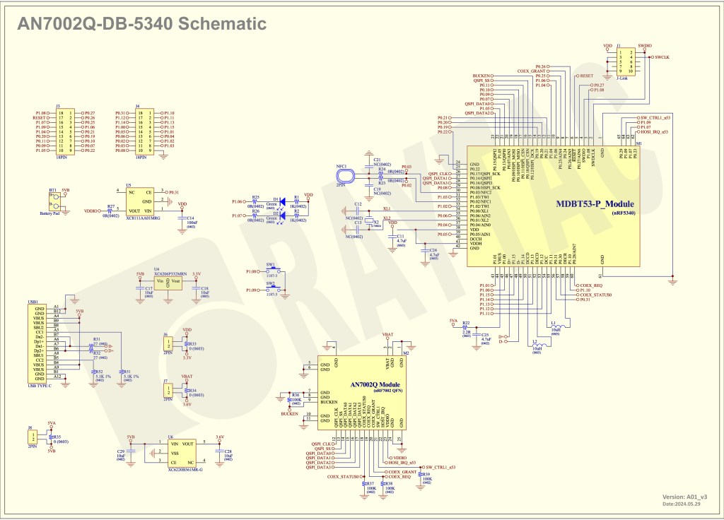
Currently, the Nordic Wifi module – AN7002Q on Raytac’s AN7002Q-DB-5340 board isn’t loaded with a Wi-Fi MAC address. You can choose to use your own MAC address or request one from Raytac. Below is a complete tutorial for users who would like to purchase MAC addresses themselves.
Note: Raytac provides two free Wi-Fi MAC addresses (2.4GHz & 5GHz bands) for each AN7002Q module.
If you have a Raytac AN7002Q-DB-5340 demo board but have not received the Wi-Fi MAC addresses, please contact us at sales@raytac.com.
★ What is a MAC Address?
A MAC address (Media Access Control address) is a unique identifier used to identify network devices. It is typically composed of six groups of two hexadecimal digits, for example, 00:1A:2B:3C:4D:5E. The first six characters are known as the Organizationally Unique Identifier (OUI), which identifies the manufacturer or supplier of the MAC address. Manufacturers can use the OUI to identify the producer of the device.
Each network device’s MAC address should be unique. It is an important identifier used for unique identification among network devices, ensuring that devices can communicate correctly within a local area network. However, it is important to note that MAC addresses can be modified within a local network, so they should not be relied upon as the sole basis for security.
★ How to Obtain a MAC Address?
The application and distribution of MAC addresses are managed by IEEE (Institute of Electrical and Electronics Engineers). Here’s how to apply for a MAC address from IEEE:
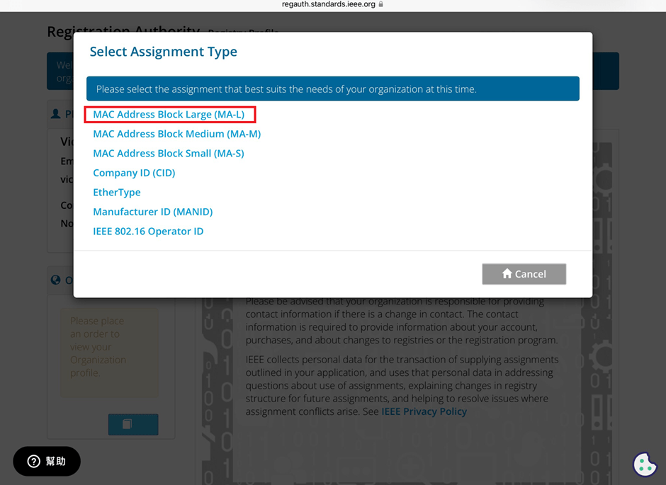
Currently, MAC addresses can only be purchased directly from the IEEE Standards Association in the United States. Depending on the quantity, they can be categorized as:
MA-L (approximately 16 million addresses)
MA-M (approximately 1 million addresses)
MA-S (4096 addresses)

★ Purchase process
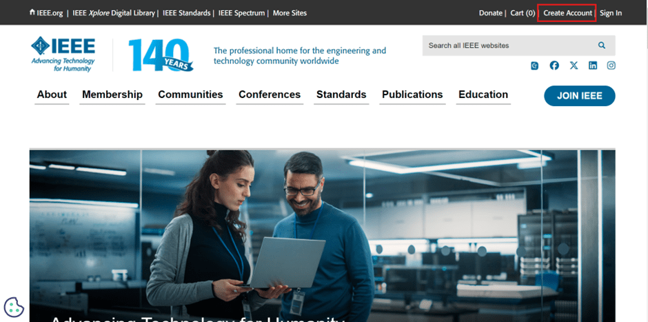
1. Register for an IEEE Account
Visit IEEE’s official website to create an account.
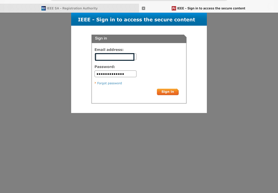
2. Log in and go to the MAC Address Purchase Page
After logging in, navigate to the MAC address purchase page: IEEE MAC Address Purchase
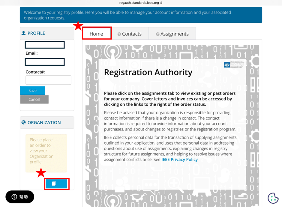
3. Select the number of MAC Addresses to purchase.
4. Fill in your purchase information by providing the required details.

5. Confirm confidentiality
Confirm whether the MAC address purchase is confidential. If you are purchasing publicly registered MA-L, select “No" for this option.

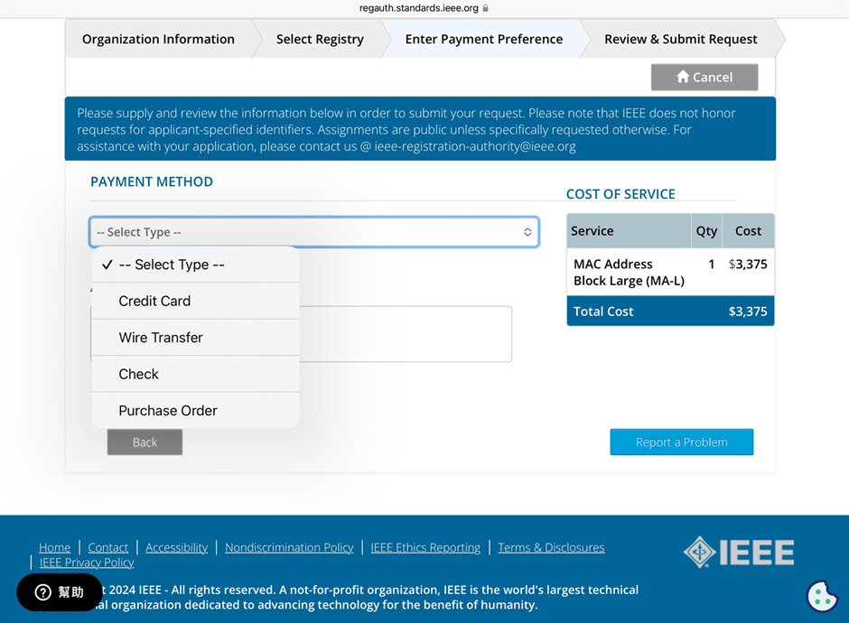
6. Choose payment method
IEEE accepts several payment methods, including mailing a U.S. bank draft, wire transfer in U.S. dollars, and online credit card payment.
7. Receive your OUI
Within 7 working days, IEEE will send an email to the registered email address containing the purchased OUI.

After obtaining the OUI, you can retrieve all the purchased MAC addresses using code and then import them into a database or Excel for management.
Edited by Sales Manager: Ms. Vicky Huang
Raytac Corporation 勁達國際電子股份有限公司
A Bluetooth, Wi-Fi, and LoRa Module Maker based on
Nordic nRF54; nRF53: nRF52; nRF51; nRF7002
Semtech Specification: SX1262
Bluetooth Specification: BT5.4 ; BT5.3 ; BT5.2.
Wi-Fi Specification: Wi-Fi 6
LoRa Specification: LoRaWAN
All products are FCC/IC/CE/Telec/KC/RCM/SRRC/NCC/WPC Pre-Certified.
http://www.raytac.com
email: sales@raytac.com
Tel: +886-2-3234-0208