Raytac Corporation would like to inform all customers and partners of an official Product Change Notice: PCN-25100801 regarding the following product series:
Affected Series MDBT50Q-RX Series (nRF52840/833 based USB-A dongles)
Update of Raytac’s company logo on the nameplate, and
Addition of NCC logo on the back label.
There are no changes to product function, performance, quality, form factor, or safety compliances. All existing certifications and technical documentations remain valid.
We kindly invite our customers, distributors, and partners to update your records accordingly. For any questions or support regarding this update, feel free to reach out via: service@raytac.com.
Full details of the PCN please see below(Click on the images to zoom in). Remark: Please take note of the final shipment date.
Edited by Business Development Manager: Tony Yin
Raytac Corporation 勁達國際電子股份有限公司 / Raytac Corporation (USA) / abietec Inc. A Bluetooth, Wi-Fi, and LoRa Module Maker/ODM & OEM Manufacturer based on Nordic nRF54; nRF53: nRF52; nRF51; nRF7002 Semtech Specification: SX1262
In this article, Stanley Huang, MSc, Deputy Manager of Firmware Development at Raytac, shares insights on how Raytac’s modules and development kits strengthen the Zephyr ecosystem.
[Stanley Huang, New Taipei City] When we talk about open-source platforms like Zephyr RTOS, most people immediately think of major chip manufacturers such as ST Micro, NXP, or Nordic. But to me, what truly makes Zephyr famous amongst the developer community is through modules that developers can actually touch: those they can instantly plug in and start using right away. In these terms, Raytac is one of the most underrated and important contributors in this ecosystem.
Raytac Modules Make Zephyr More Accessible Instead of being a chip vendor, we specialize in producing high-quality, globally certified modules – especially Bluetooth and Wi-Fi modules based on Nordic chipsets, such as the AN7002Q, AN54LQ, AN54LV, MDBT53, MDBT50Q, and MDBT42Q. All these modules are already certified with Regional RF compliances(FCC, IC, CE, KC, etc.) and the latest Bluetooth Specifications, offering developers the assurance of “plug and play” and “production-ready” solutions. We assure that our modules have become one of the easiest platforms for Zephyr developers to test BLE functionality.
I paired Zephyr with Raytac’s MDBT50Q-DB-40 development board when I first applied Zephyr in a BLE Peripheral project . With a simple west build -b nrf52840dk_nrf52840 followed by flashing the firmware using J-Link or nRF Connect for Desktop, the BLE beacon immediately showed up on my phone. Clean, simple, noise-free, and developer-friendly – that’s Raytac’s style.
Modules play an invaluable role in product development Many would say Raytac only makes modules and the real core is still Nordic’s SoC. But I believe that in an open-source system like Zephyr, the hardware that helps your project runs first is that which contributes the most. Our Zephyr-registered development kits eliminate the hassles of manual soldering, regulatory certification, and antenna design, allowing engineers to fully focus on developing applications based on Zephyr. They can run Zephyr’s BLE peripheral, central, GATT, and HCI samples directly on the Raytac kits that act as a one-stop hardware solution. In many ways, Raytac has pushed Zephyr’s usability a significant step forward.
Raytac Also Expands Zephyr’s Application Horizon Many of Raytac’s modules are ultra-compact- ideal for wearables, smart sensors, and low-power beacons…etc. These are the scenarios where Zephyr excels, and Raytac’s modules provide the physical platform to enable companies to build their “dream devices". When running Zephyr on a tiny module like the AN54LV-15(Product Link), developers will be amazed that something smaller than a piece of corn kernel can run a full RTOS, manage the BLE stack, trigger timers, drive I2C sensors, and even connect to the cloud, all by itself. This combination doesn’t just make development easier – it inspires developers to realize that: “they can build their projects using Raytac’s hardware.”
Raytac may not be the star, but we’re always ready for you On Zephyr’s main stage, companies like Nordic, STM, and Intel take the spotlight, but Raytac plays an essential supporting role – supporting the performance from behind the scenes. We offer stable, high quality, and low-power platforms, giving every line of Zephyr code a place to run and every feature a cornerstone. Our greatest value lies in helping developers skip antenna design and RF interference concerns – so they can jump right into the Zephyr ecosystem with ease.
Our products deliver the reliability you need and the efficiency you expect.
Raytac would like to officially announce a Product Change Notice (PCN) for our Bluetooth Low Energy modules based on Nordic Semiconductor’s nRF54L series SoCs, including the nRF54L15, nRF54L10, and nRF54L05. This update specifically concerns the Part Number (PN) changes for improved clarity and product identification across our lineup.
Affected Models Please refer to the table/list below for the full details of the updated part numbers. (Click on the image to zoom in)
Reminder This PCN involves part number naming only. There are no changes to product function, performance, quality, form factor, or safety compliance. All existing certifications and technical documentations remain valid.
We kindly invite our customers, distributors, and partners to update your records accordingly. For any questions or support regarding this update, feel free to reach out via: service@raytac.com
Raytac Corporation 勁達國際電子股份有限公司 / Raytac Corporation (USA) A Bluetooth, Wi-Fi, and LoRa Module Maker/ODM & OEM Manufacturer based on Nordic nRF54; nRF53: nRF52; nRF51; nRF7002 Semtech Specification: SX1262
This guide teaches you how to use MCUboot for DFU (Device Firmware Update), Combined with nRF Connect SDK (NCS) V2.9.1 to upgrade firmware on Raytac’s MDBT50Q series modules.
Table of contents:
Hardware Set Up
Software Kits resource download & install
Compile and load the program a. Open VS Code b. Project setup c. Setup the situation for DFU over UART or DFU over USB d. Start compiling your project e. Load your compiled program into the MDBT50Q-DB-40 demo board
Install nRF Connect for Desktop ➔ install Programmer and Toolchain Manager.
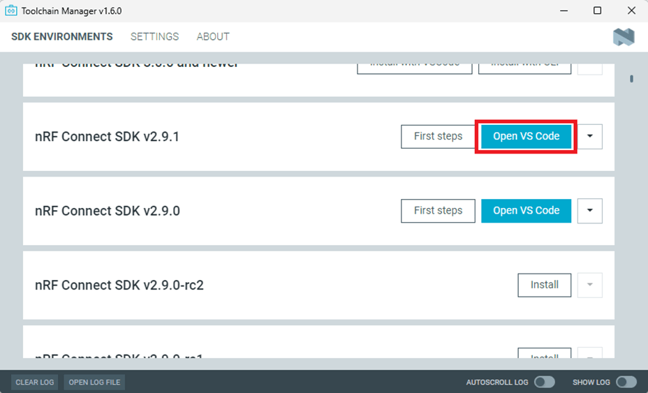
Open Toolchain Manager and install SDK V2.9.1.
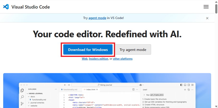
Install Visual Studio Code
3. Compile and load the program a. Open VS Code(Visual Studio Code)
Note: If it’s your first time using the software: after installing all the extensions, you should see the same on your screen.
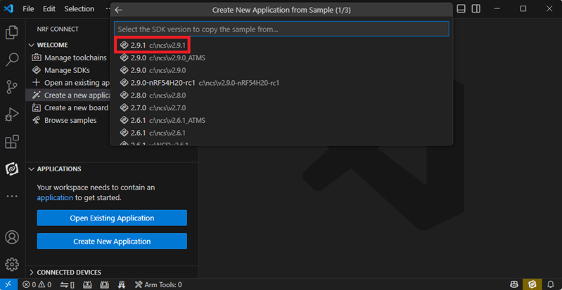
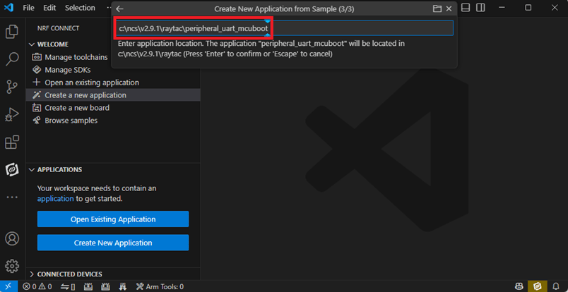
b. Project setup b.1 Create an example code(In this article: peripheral_uart) Please refer to the following steps: Create a new application ➔ Copy a sample ➔ NCS V2.9.1
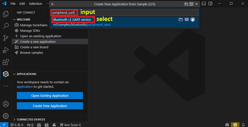
b.2 Name the Project: peripheral_uart Input peripheral_uart and the corresponding example program will appear in the options section below.
Note: We named the project peripheral_uart_mcuboot to distinguish it. This project will create a directory named peripheral_uart_mcuboot.
c.Build an environment for DFU over UART or DFU over USB – Create a new application ➔ Open
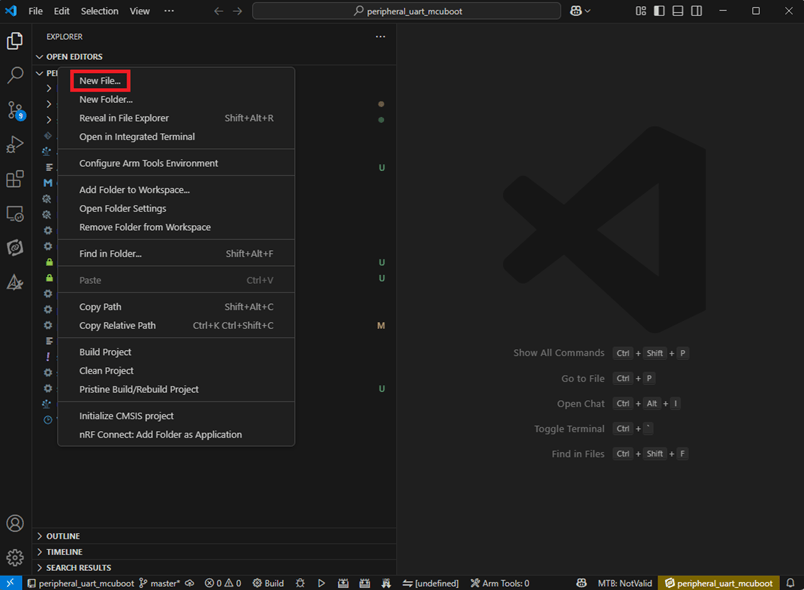
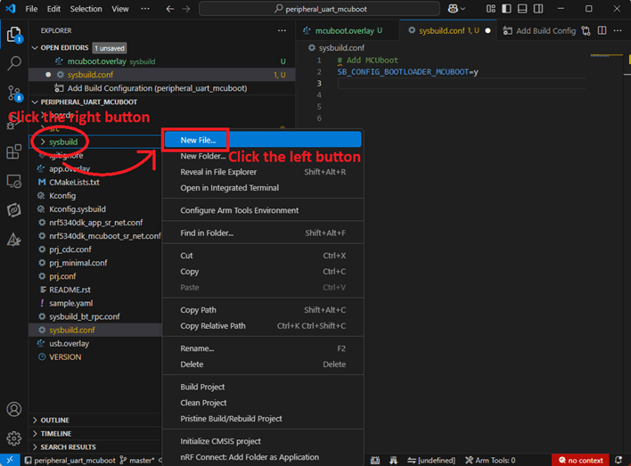
Right click on the project name you just created (peripheral_uart_mcuboot), a pop-up menu will appear. Select the first option “Show in Explorer" from the pop-up menu to display all project files.
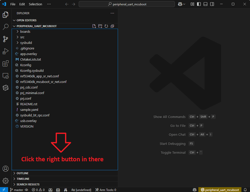
Then select New File to create a sysbuild.conf file.
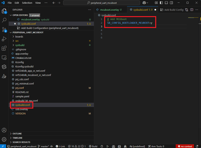
select sysbuild.conf, left-click on it, and a blank box will show.
Input the file name and write: SB_CONFIG_BOOTLOADER_MCUBOOT=y
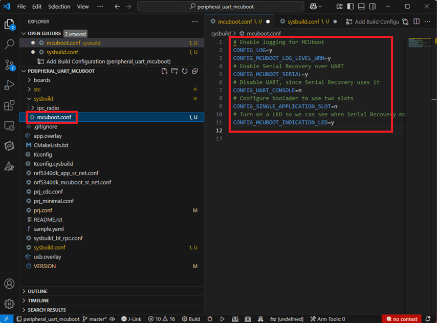
Parameters and instructions Add a new file mcuboot.conf, in the sysbuild folder, and input the following parameters into the file. (Add relevant parameters according to UART or USB) (Note: Please be informed if you want to use DFU over UART in the end, you should use UART when you first create the environment. Similarly, if you want to use DFU over USB, you should create the USB environment at the beginning.)
For DFU over UART # Enable logging for MCUboot CONFIG_LOG=y CONFIG_MCUBOOT_LOG_LEVEL_WRN=y # Enable Serial Recovery over UART CONFIG_MCUBOOT_SERIAL=y # Disable UART, since Serial Recovery uses it CONFIG_UART_CONSOLE=n # Configure the bootloader to use two slots CONFIG_SINGLE_APPLICATION_SLOT=n # Turn on a LED so we can see when Serial Recovery mode is active CONFIG_MCUBOOT_INDICATION_LED=y
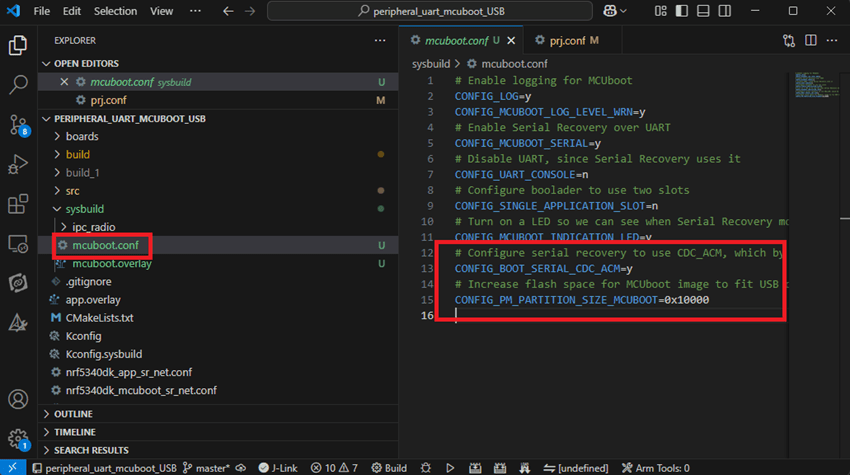
For DFU over USB # Enable logging for MCUboot CONFIG_LOG=y CONFIG_MCUBOOT_LOG_LEVEL_WRN=y # Enable Serial Recovery over UART CONFIG_MCUBOOT_SERIAL=y # Disable UART, since Serial Recovery uses it CONFIG_UART_CONSOLE=n # Configure bootloader to use two slots CONFIG_SINGLE_APPLICATION_SLOT=n # Turn on a LED so we can see when Serial Recovery mode is active CONFIG_MCUBOOT_INDICATION_LED=y # Configure serial recovery to use CDC_ACM, which by default uses the USB CONFIG_BOOT_SERIAL_CDC_ACM=y # Increase flash space for the MCUboot image to fit USB drivers CONFIG_PM_PARTITION_SIZE_MCUBOOT=0x10000
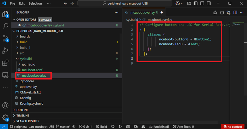
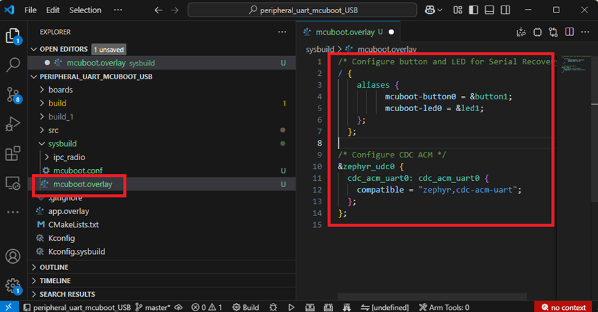
Create a new file: mcuboot.overlay and add the following parameters.
For DFU over UART /* Configure button and LED for Serial Recovery */ / { aliases { mcuboot-button0 = &button0; mcuboot-led0 = &led0; }; };
For DFU over USB /* Configure button and LED for Serial Recovery */ / { aliases { mcuboot-button0 = &button0; mcuboot-led0 = &led0; }; }; /* Configure CDC ACM */ &zephyr_udc0 { cdc_acm_uart0: cdc_acm_uart0 { compatible = “zephyr,cdc-acm-uart"; }; };
Note: if you use DFU over USB, please enable the USB subsystem in prj.conf.
After all the setup is completed, you can start compiling your project.
d. Start compiling your project Add Build Configuration ➔ Select target board ➔ In this example, choose raytac_mdbt50q_db_40/nrf52840.
Start compiling by clicking “Generate and Build" at the bottom-right corner.
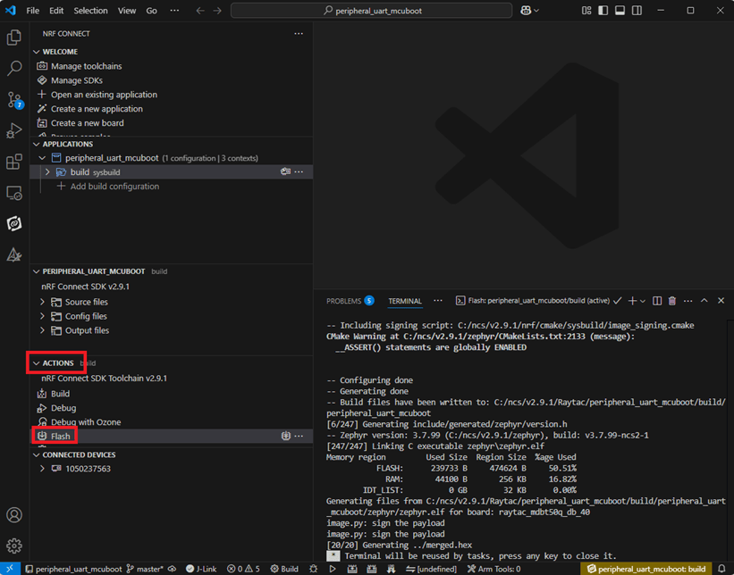
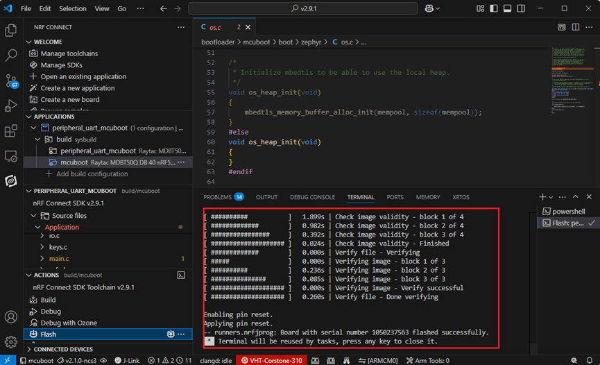
e. Load your compiled program into the MDBT50Q-DB-40 demo board After compiling without error, select the flash function to load your program into the MDBT50Q-DB-40 demo board.
If the below is shown, it means that you have successfully loaded your program into the demo board.
4. DFU to MDBT50Q-DB-40 through UART / USB DFU over UART Hold the SW2 button then plug the power into the USB connector. The system will enter the bootloader mode. You can then DFU the new firmware via the UART.
DFU over USB If you update your firmware through USB, please also hold the SW2 button and connect the USB cable.
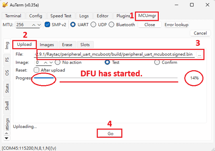
Steps: Select the tab Config to set the correct COM port.
Follow the sequences in the below screenshot.
You can use the file peripheral_uart_mcuboot.signed.bin for testing. It is located in peripheral_uart_mcuboot/build. Then follow the sequences in the below screenshot. DFU will be completed when the progress reaches 100%.
6. DFU using your custom keys When you compile the code, you will see the below warning. Reason: It’s required to have your own private key to ensure your product’s security. Following are the steps to enable security features.
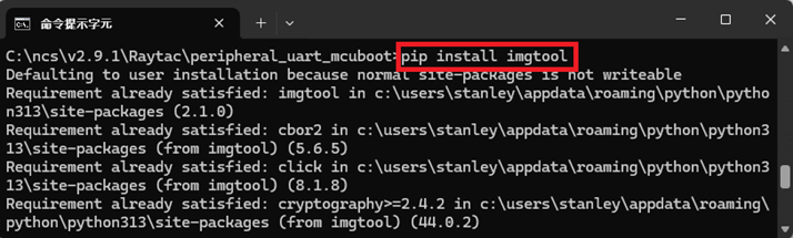
Step 1. Create the key First, install the imgtool program using pip.
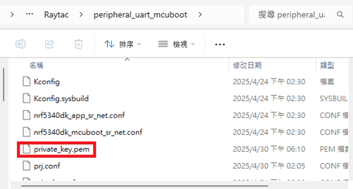
Then use the following command to generate your private key in your project folder. After the private key is generated, you can access it in your directory.
Step 2. Configure the project to use this key in sysbuild.conf
# Add MCUboot SB_CONFIG_BOOTLOADER_MCUBOOT=y #Add private key for MCUboot SB_CONFIG_BOOT_SIGNATURE_KEY_FILE="\${APP_DIR}/private_key.pem" # Configure key type SB_CONFIG_BOOT_SIGNATURE_TYPE_ECDSA_P256=y
Step 3. Build and flash the project again. Your firmware will have security features.
Edited by Account Manager: Mr. Welson Kuo
Raytac Corporation 勁達國際電子股份有限公司 / Raytac Corporation (USA) A Bluetooth, Wi-Fi, and LoRa Module Maker/ODM & OEM Manufacturer based on Nordic nRF54; nRF53: nRF52; nRF51; nRF7002 Semtech Specification: SX1262
[2025.02.19] Raytac Corporation is proud to announce that our application for Wi-Fi Alliance (WFA) certification on the AN7002Q series(based on Nordic’s nRF7002 IC) has been successfully approved. This achievement reinforces our commitment to providing high-quality, reliable, and standard-compliant wireless solutions. By leveraging this certification, our modules ensure seamless interoperability, enhanced security, and superior performance for a wide range of IoT applications.
Advantages of Using Raytac Modules with WFA Certification:
Reliable and Secure Connectivity – Ensures seamless communication with other Wi-Fi-certified devices while meeting industry-leading security standards for stable and secure data transmission. Faster Time-to-Market – Pre-certified modules simplify compliance processes, reducing development time. Global Market Access – Certification helps meet regulatory requirements in multiple regions, expanding business opportunities. Significant Cost-Saving – Compared to the chip-on-board approach, using Raytac’s Wi-Fi module allows direct access to the Derivative programs(please click here for more descriptions), leveraging Raytac’s CID to minimize certification costs and save time-to-market.
To learn more about Wi-Fi certifications and Wi-Fi + BLE applications, feel free to contact us anytime at sales@raytac.com.
Edited by Account Manager: Ms. Mandy Chao
Raytac Corporation 勁達國際電子股份有限公司 A Bluetooth, Wi-Fi, and LoRa Module Maker based on Nordic nRF54; nRF53: nRF52; nRF51; nRF7002 Semtech Specification: SX1262
Uncertainties in Bluetooth Application Development Bluetooth’s growing popularity comes with challenges during development. Common issues include hardware instability, software incompatibilities, and environmental interference. Accurate issue identification and resolution are keys to successful development.
Common Uncertainties Unstable Connections: Disruptions from wireless signals or physical obstacles. Pairing Failures: Devices unable to establish connections. Data Errors: Packet loss or corruption during transmission. Compatibility Problems: Protocol version mismatches affecting interoperability.
Efficient Bluetooth Issue Analysis Challenges like transmission speed limitations, data loss, connection failures, or protocol violations can arise. As Bluetooth signals travel wirelessly, precise analysis requires specialized tools. Nordic offers firmware integrated with Wireshark, flashable onto the Raytac MDBT50Q-CX-40 Dongle, enabling engineers to capture and analyze Bluetooth broadcast signals via USB. This setup streamlines issue identification and resolution. Below’s how to configure the Dongle for Wireshark reception.
Step 3: Press and hold the button on MDBT50Q-CX-40 and plug it into a PC USB port. Bootloader mode will be activated after the LED light is turned on. Then flash the firmware using nRF Programmer.
Step 4: Open the nRF Programmer and follow the below steps: Select the Device:
The device will appear as the name shown in below:
Add Firmware File:
Load sniffer_nrf52840dongle_nrf52840_4.1.1.hex into the Programmer:
Press “Write" to flash the firmware. After flashing, press “Select Device" again. If the Device name appears as nRF Sniffer for Bluetooth, the flashing is successful.
Set Up Wireshark Software Environment Step 1: Download & install nRF-Util: https://www.nordicsemi.com/Products/Development-tools/nRF-Util Step 2: Open MS-DOS and use the command nrfutil list to check if the ble-sniffer item is available. If not, install it using nrfutil install ble-sniffer.
Step 3: Download and Install Wireshark: https://www.wireshark.org/download.html. Step 4: Open Wireshark and navigate to: Help → About Wireshark → Folders. Step 5: Locate the string under Personal Extcap Path for the extcap directory, which will be an empty folder.
Step 6: Copy the files from nrf_sniffer_for_bluetooth_le_4.1.1\extcap (downloaded earlier) into Wireshark\extcap directory.
Step 7: After reopening, you should see an interface with a configurable icon next to the dongle.
Step 8: Edit → Configuration Profiles → Import → From Directory → Navigate to the directory nrf_sniffer_for_bluetooth_le_4.1.1\Profile_nRF_Sniffer_Bluetooth_LE and click “Select Folder".
Step 9: The profile will be imported. Click OK to confirm.
After all the above is done, the setup shall be completed.
Capturing and analyzing Bluetooth packets After launching the program, you can see the following devices and Dongle settings. Double-click to start the packet capture process:
If you want to capture packets with PHY=125K, you can use the following settings:
Packet Analysis Method In Wireshark, select the device from the “Device" menu to capture and analyze broadcast packets.
User Cases – What sniffer can offer 1. Disconnection when transmitting over 20 bytes between Tablet and Raytac’s AT-Command Module: Through sniffer analysis, it was discovered that Raytac’s module requested a packet length of 251 bytes, but the tablet’s TX setting was limited to 27 bytes.
2. Broadcast Device Name containing invisible characters: The device could connect using a mobile app but failed to connect using Central’s code. From the sniffer interface shown below, the device name length is 11, but the Length field shows 13. The actual data length (Type length + Device Name) = 1 + 11 = 12, indicating an issue with the program’s broadcast name length.
3. Incorrect parameter settings causing issues with throughput or packet reception: Improper settings can lead to reduced throughput, incorrect data reception, or disconnections. The diagram below shows a correct setup with high-volume data transmission. The Protocol Length is 251, and the data transmission intervals are consistent, achieving optimal throughput.
Summary Mastering hardware and software setups and effectively using packet analysis tools can boost development efficiency and enable high-performance Bluetooth applications.
B. Comparison among nRF54L15/ nRF5340/ nRF52840/ nRF52832 SoC modules
If you are familiar with Nordic nRF52, nRF53 module series, you will have better idea to tell the difference heading to NRF54L series by referring to the chart as below. (Click on the picture to zoom in)
C. Get started with nRF54L15 development (NCS 2.8.0)
Preparation of Hardware: 1. 1x Nordic NRF54L15 DK (PCA10156-0.9.1) (Note: If you have PDK (PCA10156-0.8.1) on hand, it can be done in trial phase) 2. 1x Raytac AN54LQ-DB-15 3. 1x IDC Ribbon wire 4. 2x USB-C connector wires (for powering the kit up)
Note: Using Nordic nRF54L15DK / nRF54L15PDK as debugging tool and Raytac Demo board-AN54LQ-DB-15 as simulated carrier board(main board) to proceed the program of nRF54L15 for code compiling and development.
Tips: Please align the red edge of Ribbon at side of 1 in connector J1.
Step 1 —- Connected NRF54L15 DK and AN54LQ-DB-15 by IDC Ribbon wire Step 2 —- Powering on both NRF54L15 DK and AN54LQ-DB-15 by USB-C connector
<< Schematic of AN54LQ-DB-15(Updated on 21-Jan-2025) >>(Click on the picture to zoom in)
Preparation 1. Prepared with the latest version of nRF Connect for Desktop and Select version Windows 64-bit – 5.1.0 2. Prepared with the latest version of nRF Command Line Tools and Select version Windows x86 64-10.24.2 **Note: SEGGER J-LINK Upgrade message might pop up while you’re doing above download.
3. Locate all the necessary kits for programming in PC (Check Software/Application list)
Get started with building your program
Intro: The development tool of nRF Connect SDK(NCS) equipped with free VS (Visual Studio) Code IDE for firmware compile and programming. Note: it is highly recommended to apply NCS 2.8.0 for advanced features of nRF54L15.
Step 1 —- Activate your “nRF Connect for Desktop” >> “Toolchain Manager” >> “Open” >> “Install”
Step 2 —- You will find multiple options of NCS V x.x.x in the tool, we’re using NCS v2.8.0 as example to run sample code of nRF54L15.
Step 3 —- Make sure the NCS v2.8.0 is installed at same directory with compiling system. (the root of Open VS Code) (This is using C:\ncs as example.)
In case to organize the files, do “Select directory’” and “Confirm”.
Step 4 —- After nRF Connect SDK v2.8.0 Download ready , go “Open VS Code”.
Step 5 —- Go “Open Existing Application” , and activate example code: Bluetooth > peripheral_uart
Step 6 —- Moving to program build & compiling by selecting dev kit: nrf54l15dk/nrf54l15/cpuapp
Step 7 —- You will get a .hex file after the above programming compiling process.
Step 8 —- Functions are available for during the code compiling process under “ACTIONS” in VS Code IDE << Build >>
<< Debug >>
<< Flash >>
Firmware Programming It is feasible to do the firmware programming using nRFConnect SDK (NCS) tool. Developer may use “Programmer” to do the firmware flashing with the candidate .hex file.
Step 1 —- Execute nRF Connect for Desktop >> Programmer >> Open
“Select Device”
Select ”nRF54L15 DK”
“Add File”
Step 2 —- Select the candidate .hex file
Select “Erase & Write”
It indicates the programming process is on the way↓
The firmware programming process is done after seeing “Completed” in system Log field.
Step 3 —- Use the mobile App to make sure the Bluetooth broadcasting is functioning after the firmware flashing process is successfully done to the module.
D. Channel Sounding Preview
What is Channel Sounding? —- Advance the “Find My” feature into next level accuracy Have you ever concerned about the distance accuracy when you’re using RSSI to get the distance between devices and to evaluate the transmission distance with legacy Bluetooth module? Nordic NRF54 solution has taken us into next level with Channel Sounding feature that achieves the “centimeter-level” distance accuracy. Early implement achieves 10-20cm in the record.
Credit: Bluetooth Alliance
How does Bluetooth Channel Sounding work? Bluetooth Channel Sounding implemented with Phased-Based Ranging (PBR) & Round-trip time (RTT)(the concept idea of TOF time of flight) algorithm to achieve a higher precision of measuring distance between 2 devices.
Phased-Based Ranging (PBR): Signal has been sent between initiator and reflector with multiple frequency to increase measuring accuracy.
Credit: Bluetooth Alliance
Round-trip time (RTT): It’s the concept of utilizing TOA (Time of arrival). Using TOD(Time of departure) & TOA to measure the timing during the packet transmission between devices.
Credit: Bluetooth Alliance
Potential applications: Personal item finding Secure access control Smart lock system Digital Key Asset Tracking
Currently, the Nordic Wifi module – AN7002Q on Raytac’s AN7002Q-DB-5340 board isn’t loaded with a Wi-Fi MAC address. You can choose to use your own MAC address or request one from Raytac. Below is a complete tutorial for users who would like to purchase MAC addresses themselves.
Note: Raytac provides two free Wi-Fi MAC addresses (2.4GHz & 5GHz bands) for each AN7002Q module. If you have a Raytac AN7002Q-DB-5340 demo board but have not received the Wi-Fi MAC addresses, please contact us at sales@raytac.com.
★ What is a MAC Address?
A MAC address (Media Access Control address) is a unique identifier used to identify network devices. It is typically composed of six groups of two hexadecimal digits, for example, 00:1A:2B:3C:4D:5E. The first six characters are known as the Organizationally Unique Identifier (OUI), which identifies the manufacturer or supplier of the MAC address. Manufacturers can use the OUI to identify the producer of the device.
Each network device’s MAC address should be unique. It is an important identifier used for unique identification among network devices, ensuring that devices can communicate correctly within a local area network. However, it is important to note that MAC addresses can be modified within a local network, so they should not be relied upon as the sole basis for security.
★ How to Obtain a MAC Address?
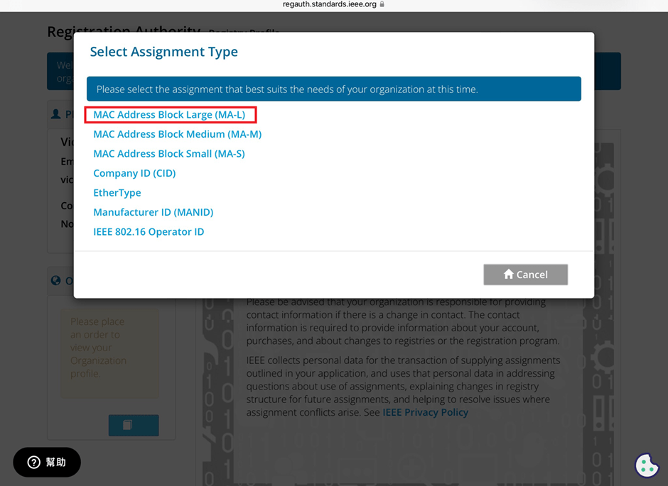
The application and distribution of MAC addresses are managed by IEEE (Institute of Electrical and Electronics Engineers). Here’s how to apply for a MAC address from IEEE: Currently, MAC addresses can only be purchased directly from the IEEE Standards Association in the United States. Depending on the quantity, they can be categorized as:
MA-L (approximately 16 million addresses) MA-M (approximately 1 million addresses) MA-S (4096 addresses)
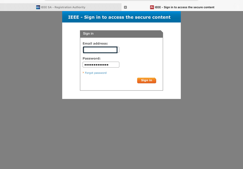
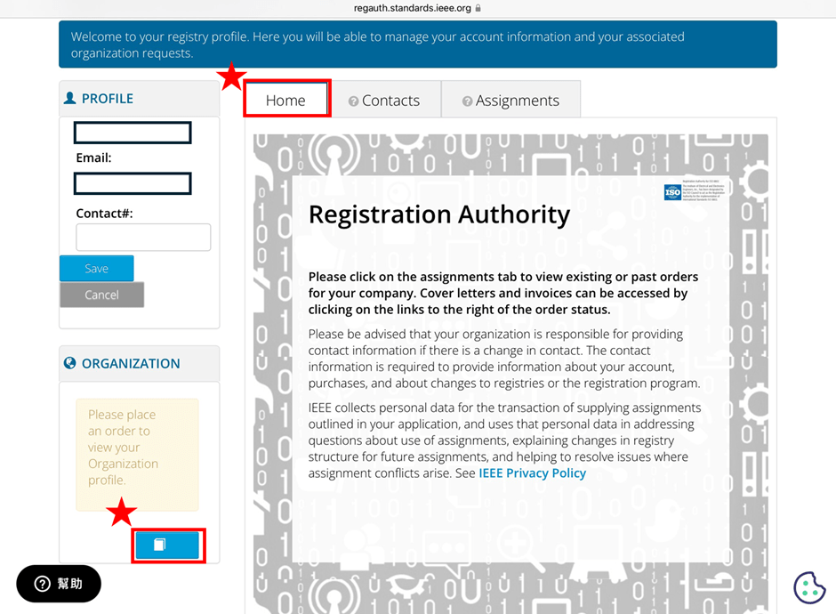
2. Log in and go to the MAC Address Purchase Page After logging in, navigate to the MAC address purchase page:IEEE MAC Address Purchase
3. Select the number of MAC Addresses to purchase.
4. Fill in your purchase information by providing the required details.
5. Confirm confidentiality Confirm whether the MAC address purchase is confidential. If you are purchasing publicly registered MA-L, select “No" for this option.
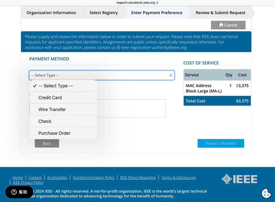
6. Choose payment method IEEE accepts several payment methods, including mailing a U.S. bank draft, wire transfer in U.S. dollars, and online credit card payment.
7. Receive your OUI Within 7 working days, IEEE will send an email to the registered email address containing the purchased OUI.
After obtaining the OUI, you can retrieve all the purchased MAC addresses using code and then import them into a database or Excel for management.
Edited by Sales Manager: Ms. Vicky Huang
Raytac Corporation 勁達國際電子股份有限公司 A Bluetooth, Wi-Fi, and LoRa Module Maker based on Nordic nRF54; nRF53: nRF52; nRF51; nRF7002 Semtech Specification: SX1262
Step 1. Execute the combine batch file in bootloader (nrf52832_bootloader_setting_merge.bat) and generate file ofnrf52832_bootloader_secure_combin_settings.hex :
@echo off title = [ J-Link Tool ] %CD% set nrfDir=C:\Program Files (x86)\Nordic Semiconductor\nrf5x\bin set BS= nrf52832_bootloader_secure_settings.hex set BL= nrf52832_xxaa_s132.hex set BSBLCombind= nrf52832_bootloader_secure_combin_settings.hex set path=%nrfDir%;%path% pause echo ———–merge image file——————- mergehex.exe -m %BS% %BL% -o %BSBLCombind% pause
Step 2. Create a Final.hex file by 3-in-1 batch file(nrf52832_3in1_merge.bat) ※Note : This hex file is created for the production line to pre-load firmware into modules prior to shipment.
@echo off title = [ J-Link Tool ] %CD% set nrfDir=C:UsersuserDesktopNordic BLEnRF5_merge toolsnRF52 bin set SD= s140_nrf52_7.2.0_softdevice.hex set BLT= nrf52832_bootloader_secure_combin_settings.hex set APP= nrf52832_xxaa.hex set SD_BLT=SD_BLT.hex set Finalfile=Final.hex set path=%nrfDir%;%path% pause echo ———–merge image file——————- mergehex.exe -m %SD% %BLT% -o %SD_BLT% pause mergehex.exe -m %SD_BLT% %APP% -o %Finalfile% pause
Step 3. Create a DFU(OTA).zip file of nrf52832_xxaa.zip ※Note : This zip file is created for end device DFU(OTA) implementation.
※Note : The “0xCB" appeared in the above DOS code(in red font) is the FWID(Firmware ID) for s140_nrf52_7.2.0_softdevice.hex; FWID can be found from the soft device documents on the Nordic website.
Step 4: Run DFU OTA (On mobile in this example)
4A. Install the nRF Connect APP on mobile, with DFU OTA file: nrf52832_xxaa.zip.(Download link)
4B. Send nrf52832_xxaa.zip via email to mobile device after combination is done on PC, then download it.
4C. Open nRF Connect APP and run connection;
4D. Execute DFU and select “Distribution packet(ZIP)", thus starting the DFU OTA process.
4E. Start DFU OTA → exit the APP after DFU OTA is completed → restart the mobile device.
Secure DFU OTA for nRF52832 solution modules: Guide to create hex/zip file for implementation Detailed links of articles: Part 1: Bootloader & Application (Click for article link) Part 2: Combining & merging built files
Technical guidelines provided by R&D Manager: Mr. MW Lee Edited by Sales Manager: Ms. Mandy Chao
Raytac Corporation 勁達國際電子股份有限公司 Raytac Corporation: A Bluetooth, Wi-Fi, and LoRa Module Maker based on Nordic nRF54; nRF53: nRF52; nRF51; nRF7002 Semtech Specification: SX1262
Here are the guidelines for users to implement Secure DFU OTA(over-the-air) while using nRF52832 Solution modules. (Click on link for Raytac nRF52832 module series)
In this article, we will be focusing on Part 1: Bootloader & Application.
Bootloader
Path: ..\nRF5_SDK_16.0.0_98a08e2\examples\dfu\secure_bootloader\pca10040_s132_ble\arm5_no_packs Specifically for nRF52832, programmers need to embed ECC(Elliptic Curve Cryptography) into the bootloader.
Step 1. ’micro_ecc_lib_nrf52.lib’ library can be found in the path below, but we need to boot it up first.
Step 2. Unzip ’micro-ecc-master.zip’ to the below path(create a new “micro-ecc” file first).
Step 3. Run ’gcc-arm-none-eabi-7-2018-q2-update-win32.exe’.
Step 4. Make sure the Environment variables in Win10 are set as below.(Follow the steps 1 to 6)
Step 5. Open DOS → run the “make” command under armgcc path → generate’micro_ecc_lib_nrf52.lib’
Step 6. Add ’micro_ecc_lib_nrf52.lib’ into folder: nRF_micro-ecc
Step 7. An error may occur while building bootloader without a public key: (Shown in red frames in below screenshot)
Step 8. How to generate the public key file in Bootloader? A. Visit DOS at path: ..\Python27\Scripts B. Then execute:
Step 9. Copy the pk[64] code from (public_key.c) into (dfu_public_key.c) (Shown in red frames in below screenshot)
※Note: Make sure to save the 3 generated files: private.pem public_key.c dfu_public_key.c
Step 10. Generate the bootloader file:nrf52832_xxaa_s132.hex after re-compiling the code files.
Application
Path: ..\nRF5_SDK_16.0.0_98a08e2\examples\ble_peripheral\ble_app_uart\pca10040\s132\arm5_no_packs Before building Application code , some amendments need to be made regarding DFU-related settings and code inside Application:
Step 1.Add code in definition in C/C++ : BL_SETTINGS_ACCESS_ONLY NRF_DFU_SVCI_ENABLED NRF_DFU_TRANSPORT_BLE=1 (Total 3 steps definitions need to be set up)
Step 2. Add the 3 paths shown below in C/C++ to make DFU work.
Step 3. Add the .c files inside red frame in (Screenshots 1 & 2) and add the 2 groups of (nRF_DFU & nRF_SVC)(Screenshot 4) under Project(Screenshot 3)
Step 4.Add code into main.c file in Application (..\examples\ble_peripheral\ble_app_uart\main.c) (Please refer to: main.c file at: ..\examples\ble_peripheral\ ble_app_buttonless_dfu)
Step 5. The code of file: sdk_config.h (..\examples\ble_peripheral\ble_app_uart\pca10040\s132\config\sdk_config.h) inside Application needs to be modified.
Step 6. Adjust the IRAM1 value in Target after implementing DFU service: Make sure the IRAM1 Value of *p_app_ram_start is modified from default: 0x20002AD8 0xD528 to 0x20002AE8 0xD518, as shown in the red frame in the bottom right corner. In this case, the program should run/advertise successfully.
Step 7. Create a file of: nrf52832_xxaa.hex after building application code files.