[New Taipei City, Taiwan – January 12, 2026] Raytac Corporation, a global leading supplier of Bluetooth, Wi-Fi, and wireless modules, announces a strategic partnership with Acal BFi(Website link) to strengthen wireless connectivity support for customers across Europe. Through this collaboration, Raytac’s portfolio of pre-certified Bluetooth® Low Energy, Wi-Fi, and Wi-Fi + Bluetooth modules will be supported by Acal BFi’s local application engineering and design-in expertise.
Raytac specializes in short-range RF connectivity, delivering production-ready wireless modules optimized for low power consumption, RF robustness, and fast system integration. Additionally, Raytac focuses on simplifying wireless design while ensuring stable performance across demanding industrial, medical, and IoT environments.
Raytac’s module portfolio includes ultra-low-power Bluetooth LE modules, Wi-Fi modules, and versatile Wi-Fi + Bluetooth combo solutions designed for reliable radio coexistence and long-term availability. All Raytac modules are pre-certified to major global regulatory standards, including CE, FCC, IC, UKCA, TELEC, KC, RCM, SRRC, NCC, and WPC, enabling customers to significantly reduce certification time and compliance risk.
“Great ideas deserve great hardware,” said Lyon Liu, CEO, Raytac. “Our mission is to remove complexity from wireless design. Together with Acal BFi, we can now support customers not only with modules, but with the integration expertise to make sure those modules perform in the real world – in metal housings, in noisy RF environments, in medical devices, in smart sensors, wherever reliability matters.”
“Bluetooth and Wi-Fi connectivity is now a core requirement in almost every market we serve – from smart infrastructure and industrial automation to healthcare and sensing,” said Matthias Beuther, Business Development Manager, Acal BFi. “By partnering with Raytac, we are adding a powerful and proven wireless platform to our portfolio. The combination of Raytac’s module technology and our application engineering expertise gives our customers a faster, lower-risk path to market.”
By working closely with Acal BFi’s IoT & Wireless Technology Centre, customers gain access to local technical support covering antenna selection and tuning, power optimization, enclosure considerations, and coexistence validation. This partnership enables a more predictable, minimal-risk path from prototype to volume production for high-reliability wireless products deployed in real-world environments.
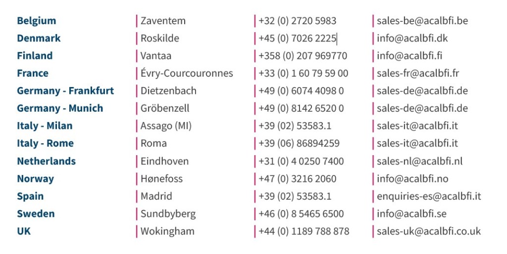
For inquires, please contact the below Acal BFi regional offices:
Edited by Business Development Manager: Tony Yin
Raytac Corporation 勁達國際電子股份有限公司 / Raytac Corporation (USA) / abietec Inc. A Bluetooth, Wi-Fi, and LoRa Module Maker/ODM & OEM Manufacturer based on Nordic nRF54; nRF53: nRF52; nRF51; nRF7002 Semtech Specification: SX1262
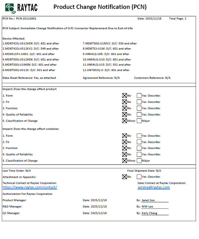
There are no changes on Form, Fit, Function, and Quality of Reliability. Only change in u.FL Connector Appearance. All existing certifications and technical documentations remain valid.
We kindly invite our customers, distributors, and partners to update your records accordingly. For any questions or support regarding this update, feel free to reach out via: sales@raytac.com.
Raytac Corporation 勁達國際電子股份有限公司 / Raytac Corporation (USA) / abietec Inc. A Bluetooth, Wi-Fi, and LoRa Module Maker/ODM & OEM Manufacturer based on Nordic nRF54; nRF53: nRF52; nRF51; nRF7002 Semtech Specification: SX1262
New U.S. Headquarter Address: 17800 Castleton Street, Suite 238, City of Industry, CA 91748, USA Phone: 626.328.3827 Our new location strengthens our operational capabilities in the United States, enabling faster logistics, enhanced customer support, and expanded service coverage. We look forward to continuing to serve our partners and customers from our new facility.
Raytac Corporation 勁達國際電子股份有限公司 / Raytac Corporation (USA) / abietec Inc. A Bluetooth, Wi-Fi, and LoRa Module Maker/ODM & OEM Manufacturer based on Nordic nRF54; nRF53: nRF52; nRF51; nRF7002 Semtech Specification: SX1262
Raytac has advanced the dev kit version of bundle offer – WIFI+BLE: AN7002Q-DB- 5340-M with an on-board flash memory(MX25R64) to create easy evaluation for Wi-Fi project developments.
[January 2026 Update] In this article, we will talk about: Project WITH External Flash MX25R64(8MB) applied – Connecting through SPI between nRF5340 module: MDBT53-1M(BLE) & nRF7002 module: AN7002Q(WIFI) – Connecting through QSPI (XIP) between MDBT53-1M and external memory MX25R64
Table of Content———————————————————————————————————
Hardware Set Up A. Project WITHOUT External Flash MX25R64 needed B. Project WITH External Flash MX25R64 needed
Software Resources & Preparations
Firmware Build & Compile A. Project WITHOUT External Flash MX25R64 needed B. Project WITH External Flash MX25R64 needed
Note: Pease make sure to have both “Nordic nRF5340-DK” and “AN7002Q-DB-5340-M”connected and running during the WIFI+BLE (nRF7002+nRF5340) project development.
Hardware Network: IDC Ribbon Wire(J-Link Cable): Connect nRF5340-DK to AN7002Q-DB-5340-M USB Wire –Type C USB: Power supply to AN7002Q-DB-5340-M through USB TYPE-C USB Wire-Micro USB: Power supply to nRF5340-DK through Micro USB
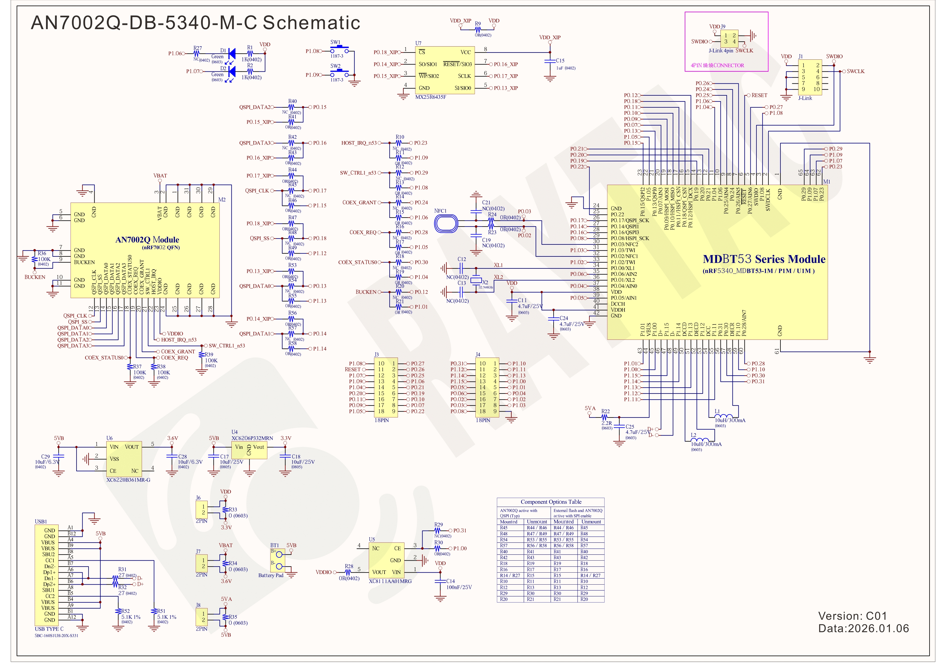
Schematic diagram of AN7002Q-DB-5340-M can be referenced for design as follows. *nRF7002 module <- SPI -> nRF5340 module *MX256R NOR Flahs <-QSPI-> nRF7002 module (Click on the image to zoom in.)
!! Important Note:!! The circuit of SW1(p1.08)/SW2(p1.09)/LED1(p1.06) on AN7002Q-DB-5340-M is NOT COMPATIBLE to Nordic WI-FI Control Pin of swctrl1(p1.08)/host_irq(p1.09)/grant(p1.06). In this case, if you’re working with external flash MX25R64 for the WIFI project, Please avoid pin SW1/SW2/LED1 usage while LED2(p1.07) remains available as normal usage. For the PCB design of end product/end device(mounted with AN7002Q & MDBT53 modules), the switch & LED should be configured to be: SW1(p0.23)/SW2(p0.24)/LED1(p0.28).
Step 1: Prepared with the latest version of nRF Connect for Desktop, using Windows 64-bit – 5.2.0 Step 2: Prepared with the latest version of Command Line Tools, using Windows X86 64 – 10.24.2
**Note: SEGGER J-LINK Upgrade message might pop up while you’re doing above downloads.
Step 3: Locate all the necessary kits for programming in PC
3. Firmware Build & Compile After you download and set up nRFConnect SDK (NCS), you will be able to apply free VS (Visual Studio) Code IDE as firmware programming tool.
The below example uses NCS v3.1.1 and runs the program under: C:\ncs
Step 1: Start with a Wi-Fi Scan project and run the program under: C:\ncs\v3.1.1\raytac <<Create a new application and Copy a sample>>
Step 2: Select SDK v3.1.1 to copy the sample
Step 3: Select example by entering keyword: wifi scan(Wi-Fi Scan)
Step 4: Enter application location: C:\ncs\v3.1.1\raytac and name the project as: wifi_scan_uart_dfu
Step 5: Open an existing application and find the registered project: wifi_scan_uart_dfu
Step 6: How to activate the Devicetree setting of Wi-Fi nRF7002 and Create file:nrf5340dk_nrf5340_cpuapp.overlay Code example is as follows: / { chosen { aliases { /delete-node/ leds; /delete-node/ buttons; }; };
Step 7: It is required to do MCUBoot before working with DFU using External Flash Please do the code configuration in sysbuild.conf as following reference code.
SB_CONFIG_BOOTLOADER_MCUBOOT=y # DFU with UART SB_CONFIG_MCUBOOT_MODE_SINGLE_APP=n
# DFU with external flash SB_CONFIG_PM_EXTERNAL_FLASH_MCUBOOT_SECONDARY=y
Step 8: It is required to doMCUMGR before working with DFU over UART Please do the code configuration in prj.conf as following reference code.
# Enable QSPI driver for Application CONFIG_NORDIC_QSPI_NOR=y
# Enable mcumgr DFU in application CONFIG_MCUMGR=y CONFIG_NET_BUF=y CONFIG_ZCBOR=y CONFIG_CRC=y
# Enable mcumgr management for both OS and Images CONFIG_MCUMGR_GRP_OS=y CONFIG_MCUMGR_GRP_IMG=y CONFIG_FLASH=y CONFIG_IMG_MANAGER=y CONFIG_STREAM_FLASH=y CONFIG_FLASH_MAP=y
# Configure MCUMGR transport to UART CONFIG_MCUMGR_TRANSPORT_UART=y CONFIG_BASE64=y
Step 9: Add with MCUBoot setting , and create a root for sysbuild ; Build with file mucboot.overlay & file mcuboot.conf
9A. To the File: mucboot.overlay &mx25r64 { status = “okay"; };
Step 10: Create a VERSION file by referencing the following code when testing DFU over UART. VERSION_MAJOR = 99 VERSION_MINOR = 0 PATCHLEVEL = 0 VERSION_TWEAK = 0 EXTRAVERSION =
Step 14: Generate a Merged.hex file after compiling the program
Step15: You can choose Build/Debug/Flash under ACTIONS during development << Build >>
<< Debug >>
<< Flash >>
Step 16: Go to ACTIONS >> Memory report to check the memory partitions.
Now you can see partitions available in the system. mcu_secondary has already been located in MX25R64 flash memory.
4. Test/Validate DFU Process & WIFI SCAN After the firmware programmed to MDBT53 module on board, we use the USB to UART adaptor board for connecting AN7002Q-DB-5340-M through: A. MCUMGR UART to PC and through: B. WiFi Scan UART to PC respectively. Note: We suggest you finish connecting A. and B. before running tests.
Now we can run the tests.
A. DFU over UART – Using AuTerm Program 1. We can locate Image version=V99.0.0 under the current VERSION file
It also indicates Image version: 99.0.0 in MCUmgr-Slot 0.
2. Try to modify the file version from V99 to V100 under VERSION file: VERSION_MAJOR = 100
VERSION_MINOR = 0
PATCHLEVEL = 0
VERSION_TWEAK = 0
EXTRAVERSION =
And go with “Pristine Build”
3. We’re about to run DFU over UART , Please DO NOT do “Flash” or “Erase”.
Proceed with “Force reboot”
4. It’s now Version 100.0.0 in Slot 0 under MCUgr ⭢ DFU over UART successfully done!
Before it was Version 99.0.0 in Slot 1 under MCUgr.
B. WIFI SCAN – PuTTY Console WIFI SCAN credentials can be located under PC Console – PuTTY.
[New Taipei, Taiwan / Los Angeles, USA] We’re thrilled to announce that Raytac Group, including Raytac Corporation(USA) and abietec Inc., will be joining Embedded World North America 2025, in November 4-6 at the Anaheim Convention Center, CA. Come find us at Booth #5067!
This year, we’re bringing lots of exciting news: From Raytac:
Brand-new Nordic nRF54L series modules: AN54LQ and AN54LV(Product Link), built for Bluetooth® LE 6.0 with ultra-low power and strong RF performance.
A full Channel Sounding demo on how precise measurement of multipath and distance can enhance real-time location accuracy, improve signal reliability, and optimize antenna placement.
Introducing you to our Ecosystem, including all our partners and technologies used in various applications.
Discover how our modules can reduce development time and costs, making your projects more efficient.
One-on-one consultations with our experts to help you find the right solutions for your needs.
From abietec:
ODM/OEM design services for everything wireless: Bluetooth®, Wi-Fi, mmWave, LoRa, NB-IoT… You name it!
More importantly, Stop by our booth to explore new products, join fun interactive games, and win prizes!
Let Raytac & abietec be your bridge to product success, connecting great ideas with real-world wireless solutions.
We’re waiting for you at: Hall C – Level 1 Booth 5067
This guide teaches you how to use MCUboot for DFU (Device Firmware Update), Combined with nRF Connect SDK (NCS) V2.9.1 to upgrade firmware on Raytac’s MDBT50Q series modules.
Table of contents:
Hardware Set Up
Software Kits resource download & install
Compile and load the program a. Open VS Code b. Project setup c. Setup the situation for DFU over UART or DFU over USB d. Start compiling your project e. Load your compiled program into the MDBT50Q-DB-40 demo board
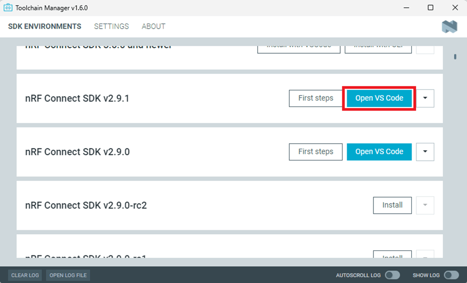
Install nRF Connect for Desktop ➔ install Programmer and Toolchain Manager.
Open Toolchain Manager and install SDK V2.9.1.
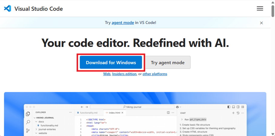
Install Visual Studio Code
3. Compile and load the program a. Open VS Code(Visual Studio Code)
Note: If it’s your first time using the software: after installing all the extensions, you should see the same on your screen.
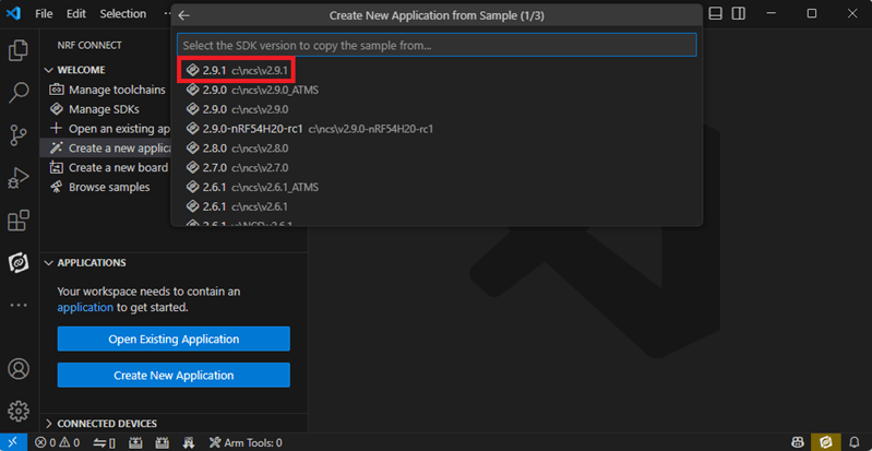
b. Project setup b.1 Create an example code(In this article: peripheral_uart) Please refer to the following steps: Create a new application ➔ Copy a sample ➔ NCS V2.9.1
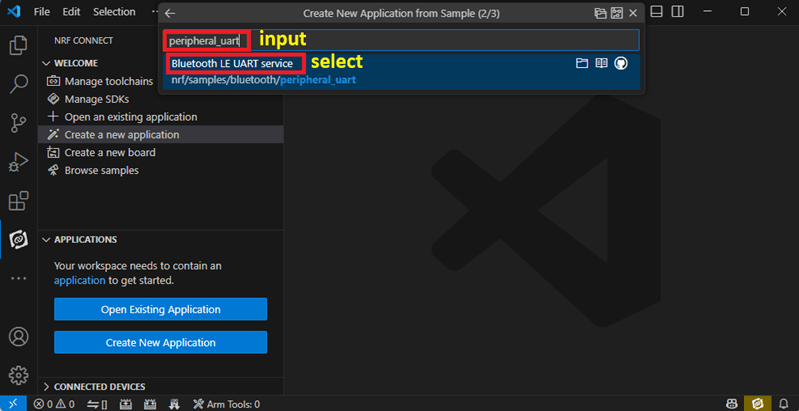
b.2 Name the Project: peripheral_uart Input peripheral_uart and the corresponding example program will appear in the options section below.
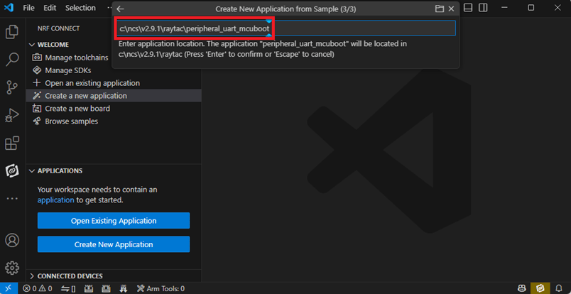
Note: We named the project peripheral_uart_mcuboot to distinguish it. This project will create a directory named peripheral_uart_mcuboot.
c.Build an environment for DFU over UART or DFU over USB – Create a new application ➔ Open
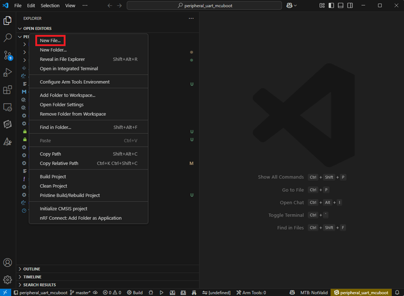
Right click on the project name you just created (peripheral_uart_mcuboot), a pop-up menu will appear. Select the first option “Show in Explorer" from the pop-up menu to display all project files.
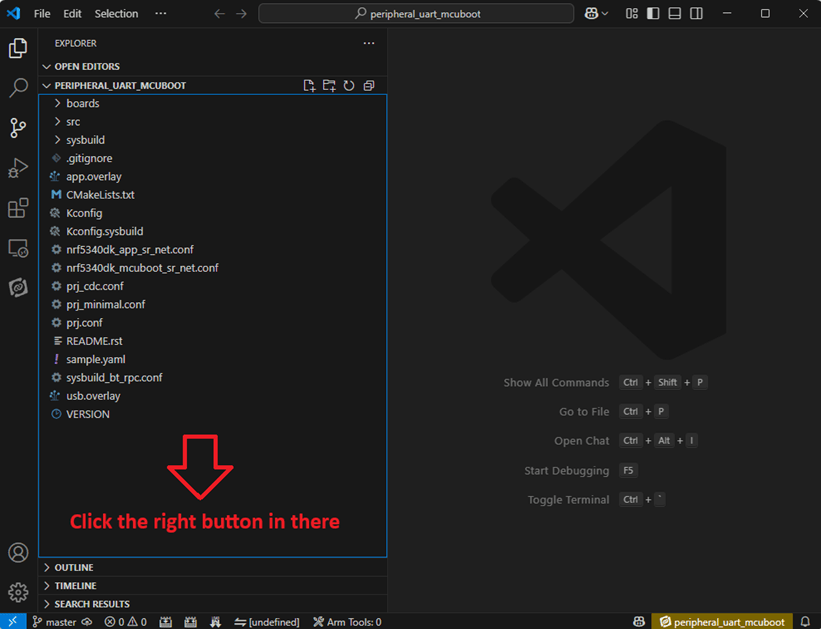
Then select New File to create a sysbuild.conf file.
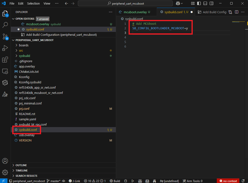
select sysbuild.conf, left-click on it, and a blank box will show.
Input the file name and write: SB_CONFIG_BOOTLOADER_MCUBOOT=y
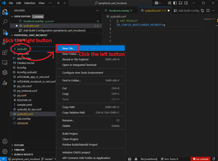
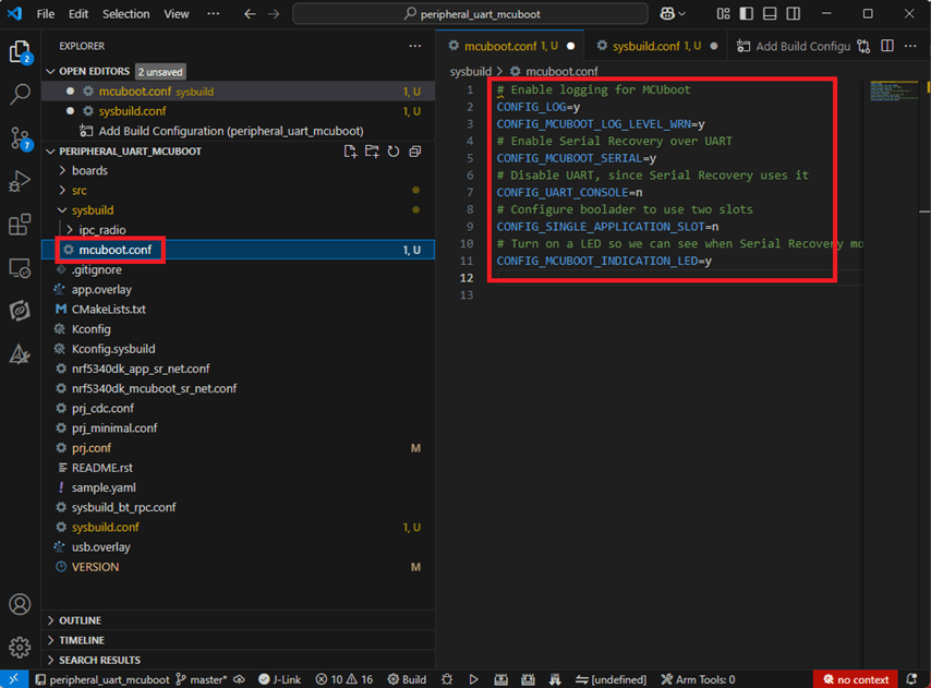
Parameters and instructions Add a new file mcuboot.conf, in the sysbuild folder, and input the following parameters into the file. (Add relevant parameters according to UART or USB) (Note: Please be informed if you want to use DFU over UART in the end, you should use UART when you first create the environment. Similarly, if you want to use DFU over USB, you should create the USB environment at the beginning.)
For DFU over UART # Enable logging for MCUboot CONFIG_LOG=y CONFIG_MCUBOOT_LOG_LEVEL_WRN=y # Enable Serial Recovery over UART CONFIG_MCUBOOT_SERIAL=y # Disable UART, since Serial Recovery uses it CONFIG_UART_CONSOLE=n # Configure the bootloader to use two slots CONFIG_SINGLE_APPLICATION_SLOT=n # Turn on a LED so we can see when Serial Recovery mode is active CONFIG_MCUBOOT_INDICATION_LED=y
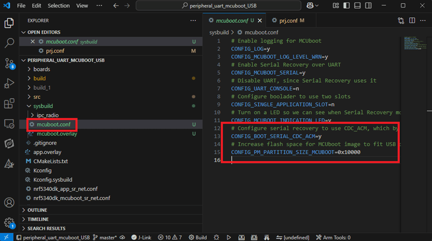
For DFU over USB # Enable logging for MCUboot CONFIG_LOG=y CONFIG_MCUBOOT_LOG_LEVEL_WRN=y # Enable Serial Recovery over UART CONFIG_MCUBOOT_SERIAL=y # Disable UART, since Serial Recovery uses it CONFIG_UART_CONSOLE=n # Configure bootloader to use two slots CONFIG_SINGLE_APPLICATION_SLOT=n # Turn on a LED so we can see when Serial Recovery mode is active CONFIG_MCUBOOT_INDICATION_LED=y # Configure serial recovery to use CDC_ACM, which by default uses the USB CONFIG_BOOT_SERIAL_CDC_ACM=y # Increase flash space for the MCUboot image to fit USB drivers CONFIG_PM_PARTITION_SIZE_MCUBOOT=0x10000
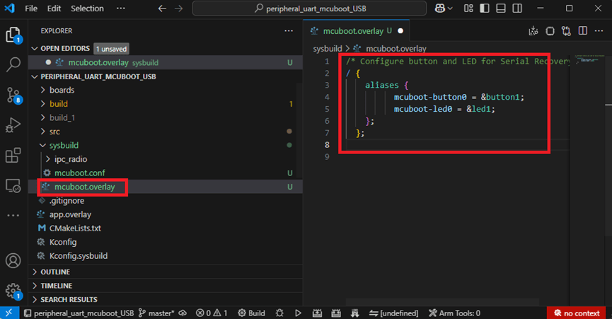
Create a new file: mcuboot.overlay and add the following parameters.
For DFU over UART /* Configure button and LED for Serial Recovery */ / { aliases { mcuboot-button0 = &button0; mcuboot-led0 = &led0; }; };
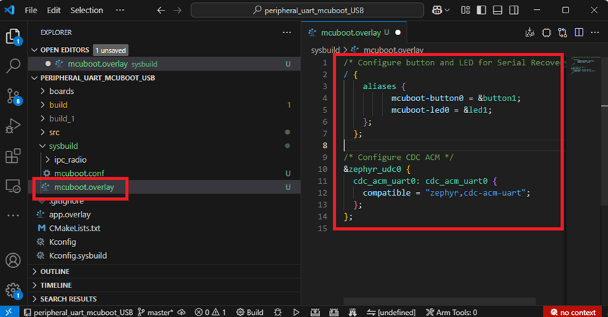
For DFU over USB /* Configure button and LED for Serial Recovery */ / { aliases { mcuboot-button0 = &button0; mcuboot-led0 = &led0; }; }; /* Configure CDC ACM */ &zephyr_udc0 { cdc_acm_uart0: cdc_acm_uart0 { compatible = “zephyr,cdc-acm-uart"; }; };
Note: if you use DFU over USB, please enable the USB subsystem in prj.conf.
After all the setup is completed, you can start compiling your project.
d. Start compiling your project Add Build Configuration ➔ Select target board ➔ In this example, choose raytac_mdbt50q_db_40/nrf52840.
Start compiling by clicking “Generate and Build" at the bottom-right corner.
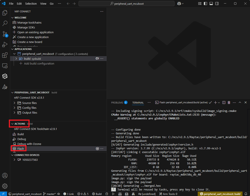
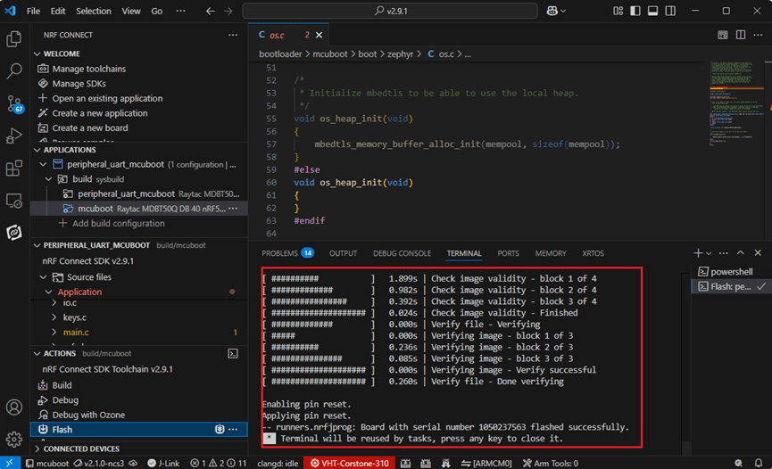
e. Load your compiled program into the MDBT50Q-DB-40 demo board After compiling without error, select the flash function to load your program into the MDBT50Q-DB-40 demo board.
If the below is shown, it means that you have successfully loaded your program into the demo board.
4. DFU to MDBT50Q-DB-40 through UART / USB DFU over UART Hold the SW2 button then plug the power into the USB connector. The system will enter the bootloader mode. You can then DFU the new firmware via the UART.
DFU over USB If you update your firmware through USB, please also hold the SW2 button and connect the USB cable.
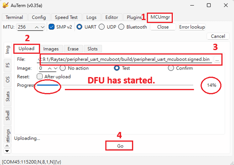
Steps: Select the tab Config to set the correct COM port.
Follow the sequences in the below screenshot.
You can use the file peripheral_uart_mcuboot.signed.bin for testing. It is located in peripheral_uart_mcuboot/build. Then follow the sequences in the below screenshot. DFU will be completed when the progress reaches 100%.
6. DFU using your custom keys When you compile the code, you will see the below warning. Reason: It’s required to have your own private key to ensure your product’s security. Following are the steps to enable security features.
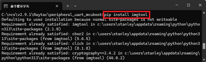
Step 1. Create the key First, install the imgtool program using pip.
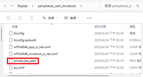
Then use the following command to generate your private key in your project folder. After the private key is generated, you can access it in your directory.
Step 2. Configure the project to use this key in sysbuild.conf
# Add MCUboot SB_CONFIG_BOOTLOADER_MCUBOOT=y #Add private key for MCUboot SB_CONFIG_BOOT_SIGNATURE_KEY_FILE="\${APP_DIR}/private_key.pem" # Configure key type SB_CONFIG_BOOT_SIGNATURE_TYPE_ECDSA_P256=y
Step 3. Build and flash the project again. Your firmware will have security features.
Edited by Account Manager: Mr. Welson Kuo
Raytac Corporation 勁達國際電子股份有限公司 / Raytac Corporation (USA) A Bluetooth, Wi-Fi, and LoRa Module Maker/ODM & OEM Manufacturer based on Nordic nRF54; nRF53: nRF52; nRF51; nRF7002 Semtech Specification: SX1262
[2025.02.19] Raytac Corporation is proud to announce that our application for Wi-Fi Alliance (WFA) certification on the AN7002Q series(based on Nordic’s nRF7002 IC) has been successfully approved. This achievement reinforces our commitment to providing high-quality, reliable, and standard-compliant wireless solutions. By leveraging this certification, our modules ensure seamless interoperability, enhanced security, and superior performance for a wide range of IoT applications.
Advantages of Using Raytac Modules with WFA Certification:
Reliable and Secure Connectivity – Ensures seamless communication with other Wi-Fi-certified devices while meeting industry-leading security standards for stable and secure data transmission. Faster Time-to-Market – Pre-certified modules simplify compliance processes, reducing development time. Global Market Access – Certification helps meet regulatory requirements in multiple regions, expanding business opportunities. Significant Cost-Saving – Compared to the chip-on-board approach, using Raytac’s Wi-Fi module allows direct access to the Derivative programs(please click here for more descriptions), leveraging Raytac’s CID to minimize certification costs and save time-to-market.
To learn more about Wi-Fi certifications and Wi-Fi + BLE applications, feel free to contact us anytime at sales@raytac.com.
Edited by Account Manager: Ms. Mandy Chao
Raytac Corporation 勁達國際電子股份有限公司 A Bluetooth, Wi-Fi, and LoRa Module Maker based on Nordic nRF54; nRF53: nRF52; nRF51; nRF7002 Semtech Specification: SX1262
We are thrilled to announce that Raytac Corporation will be participating in Embedded World 2025 from March 11 to March 13, 2025, at the Nuremberg Exhibition Centre in Germany.
IoT and Wireless technologies such as Bluetooth Low Energy (BLE), Wi-Fi, and LoRa…etc. continue to reshape industries worldwide, that’s why Raytac is at the forefront, providing cutting-edge solutions that accelerate product development. Together with our partner, Nordic Semiconductor, we offer a comprehensive range of modules designed to meet the increasing demands of today’s connected world.
This year, we have exciting innovations to showcase:
Unveiling our new service: Customized OEM/ODM designing for customers.
These are just a few of the groundbreaking solutions we’ll be unveiling. You won’t want to miss the chance to experience these with us!
What to Expect at Our Booth:
Live demonstrations showing how Raytac’s modules can be implemented in multiple industries.
Discover how our modules can reduce development time and costs, making your projects more efficient.
One-on-one consultations with our experts to help you find the right solutions for your needs.
Stop by and visit us at: HALL 3 Booth 3-111 M2M Area
We would love to connect with you and discuss how Raytac can support your next project. Whether you’re an engineer, developer, or business decision-maker, we have something for everyone at Embedded World 2025.
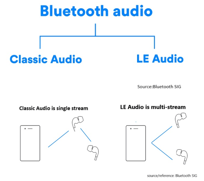
LE Audio, introduced with Bluetooth 5.2, brings significant advancements to audio technology by using the Low Complexity Communication Codec (LC3). Compared to older codecs like SBC, LC3 provides better audio quality while reducing power consumption, making it ideal for devices like wireless earphones and hearing aids. In this article, we’ll explore two key modes in LE Audio: Broadcast Isochronous Stream (BIS) and Connected Isochronous Stream (CIS). These modes cater to different use cases, offering flexible audio experiences.
What is Broadcast Isochronous Stream (BIS)?
BIS enables one-way audio broadcasting from a single source to multiple devices simultaneously without pairing. Several BIS streams can form a Broadcast Isochronous Group (BIG), allowing synchronized multi-stream transmission, ideal for environments where many users need access to the same audio content, such as events or museum tours. Any device that supports LE Audio can receive the broadcast, making it an accessible and versatile solution for shared audio experiences.
Here’s a chart including BIS and BIG:
Example Use Case: Concerts and Events Imagine attending a large outdoor concert where BIS technology is used to broadcast live music directly from the stage to the audience’s devices, such as smartphones and wireless earphones. BIS can broadcast live music from the stage directly to attendees’ devices, ensuring everyone hears the performance in real-time, regardless of location.
Example Use Case: Museum Tours In a museum setting, Broadcast Isochronous Stream (BIS) can be used to deliver audio guides directly to visitors’ smartphones or rented devices. Visitors can receive synchronized audio guides on their smartphones, enriching their experience and offering multi-language support.
What is Connected Isochronous Stream (CIS)? CIS focuses on direct, device-to-device connections. The audio stream is transmitted between paired devices with two-way communication, creating a connected and dedicated audio experience. It’s ideal for personalized experiences like hearing aids or wireless earphones. Multiple CIS streams can be synchronized using a Connected Isochronous Group (CIG) for simultaneous audio transmission while maintaining the benefits of a personalized connection.
Here’s a chart including CIS and CIG:
Example Use Case: Wireless Earphones Imagine a user connecting their wireless earphones to a smartphone via CIS. When two Bluetooth earphones are connected simultaneously, multiple CIS streams can be grouped into a Connected Isochronous Group (CIG) to achieve synchronized audio transmission across both devices and also enables high-fidelity audio streaming, ensuring clear and immersive sound. With CIS, each user can adjust volume or equalizer settings independently without impacting others, creating a truly personalized listening experience. CIS provides a significant upgrade over traditional Bluetooth audio by delivering richer sound quality with lower latency.
Example Use Case: Hearing Aids Connected Isochronous Stream (CIS) is especially beneficial for hearing aids, allowing individuals with hearing impairments to directly connect their devices to a TV, smartphone, or other audio sources. CIS enables real-time adjustments to improve speech clarity or reduce background noise, ensuring the audio is clear and effective. Users can have a closer and more immersive audio experience, which is crucial for enhancing social interactions and supporting daily activities.
How BIS and CIS are grouped into BIG and CIG
Summary
BIS vs. CIS: Which Fits Your Needs?
BIS is suitable for shared audio experiences, such as public events and guided tours, where multiple users need simultaneous access.
CIS is designed for personalized audio, offering low-latency and high-quality sound for individual users or synchronized multi-device setups.
LE Audio is set to change everyday audio experiences with richer, more versatile audio solutions. Whether it’s concerts, museums, or hearing aids, BIS and CIS provide innovative ways to enhance audio quality and efficiency.
Edited by Sales Manager: Ms. Mandy Chao
Raytac Corporation 勁達國際電子股份有限公司 A Bluetooth, Wi-Fi, and LoRa Module Maker based on Nordic nRF54; nRF53: nRF52; nRF51; nRF7002 Semtech Specification: SX1262
Currently, the Nordic Wifi module – AN7002Q on Raytac’s AN7002Q-DB-5340 board isn’t loaded with a Wi-Fi MAC address. You can choose to use your own MAC address or request one from Raytac. Below is a complete tutorial for users who would like to purchase MAC addresses themselves.
Note: Raytac provides two free Wi-Fi MAC addresses (2.4GHz & 5GHz bands) for each AN7002Q module. If you have a Raytac AN7002Q-DB-5340 demo board but have not received the Wi-Fi MAC addresses, please contact us at sales@raytac.com.
★ What is a MAC Address?
A MAC address (Media Access Control address) is a unique identifier used to identify network devices. It is typically composed of six groups of two hexadecimal digits, for example, 00:1A:2B:3C:4D:5E. The first six characters are known as the Organizationally Unique Identifier (OUI), which identifies the manufacturer or supplier of the MAC address. Manufacturers can use the OUI to identify the producer of the device.
Each network device’s MAC address should be unique. It is an important identifier used for unique identification among network devices, ensuring that devices can communicate correctly within a local area network. However, it is important to note that MAC addresses can be modified within a local network, so they should not be relied upon as the sole basis for security.
★ How to Obtain a MAC Address?
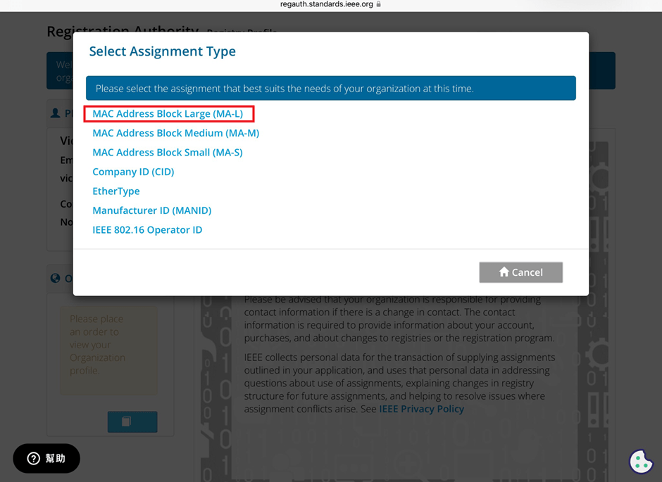
The application and distribution of MAC addresses are managed by IEEE (Institute of Electrical and Electronics Engineers). Here’s how to apply for a MAC address from IEEE: Currently, MAC addresses can only be purchased directly from the IEEE Standards Association in the United States. Depending on the quantity, they can be categorized as:
MA-L (approximately 16 million addresses) MA-M (approximately 1 million addresses) MA-S (4096 addresses)
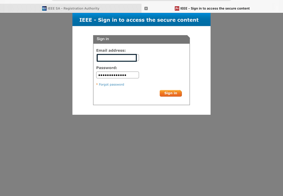
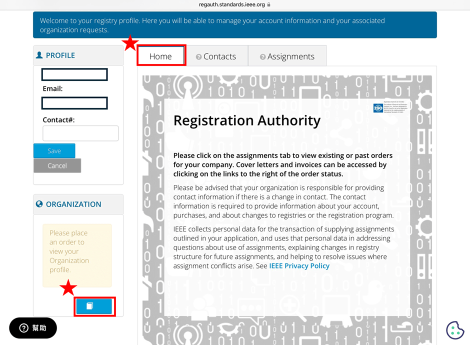
2. Log in and go to the MAC Address Purchase Page After logging in, navigate to the MAC address purchase page:IEEE MAC Address Purchase
3. Select the number of MAC Addresses to purchase.
4. Fill in your purchase information by providing the required details.
5. Confirm confidentiality Confirm whether the MAC address purchase is confidential. If you are purchasing publicly registered MA-L, select “No" for this option.
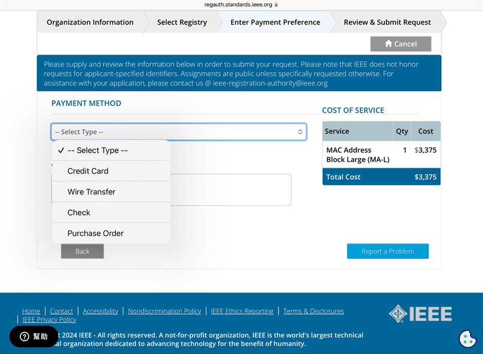
6. Choose payment method IEEE accepts several payment methods, including mailing a U.S. bank draft, wire transfer in U.S. dollars, and online credit card payment.
7. Receive your OUI Within 7 working days, IEEE will send an email to the registered email address containing the purchased OUI.
After obtaining the OUI, you can retrieve all the purchased MAC addresses using code and then import them into a database or Excel for management.
Edited by Sales Manager: Ms. Vicky Huang
Raytac Corporation 勁達國際電子股份有限公司 A Bluetooth, Wi-Fi, and LoRa Module Maker based on Nordic nRF54; nRF53: nRF52; nRF51; nRF7002 Semtech Specification: SX1262