Raytac nRF54L15 Module Series (If you want to know more or register for samples, please click me)
Table of Contents:
- nRF54L15 SoC feature brief
- Comparison among nRF54L15/ nRF5340/ nRF52840/ nRF52832 SoC modules
- Get started with nRF54L15 development (NCS 2.8.0)
- Channel Sounding preview
Next Level multi-protocol SOC -nRF54L Series

A. NEW generation nRF54L15 Soc Series
Key Features:
– ARM Cortex M33 + RISC-V co-processor 128Mhz in Nordic SoC
– Ultra compact Soc variant QFN/WLCSP, 22nm
– 2x the processing power, 3x the processing efficiency
– Industry-leading power consumption for battery-critical applications
– Global RTC wake-up from system-off
– Compatible with Raytac WIFI module -AN7002Q series
– High throughput 4MB proprietary radio mode
– Bluetooth Specification 6.0 / Support Channel sounding (Pending firmware)
– PSA(Platform Security Architecture) security level 3 qualified
Raytac’s nRF54L15 Modules
– AN54LQ-15 (Regular) & AN54LV-15(Compact)

B. Comparison among nRF54L15/ nRF5340/ nRF52840/ nRF52832 SoC modules
If you are familiar with Nordic nRF52, nRF53 module series, you will have better idea to tell the difference heading to NRF54L series by referring to the chart as below. (Click on the picture to zoom in)

C. Get started with nRF54L15 development (NCS 2.8.0)
nRF54L15 SoC Spec << access link
Nordic nRF54L15 DK << access link
Raytac AN54LQ-DB-15 << access link to be updated

Preparation of Hardware:
1. 1x Nordic NRF54L15 DK (PCA10156-0.9.1)
(Note: If you have PDK (PCA10156-0.8.1) on hand, it can be done in trial phase)
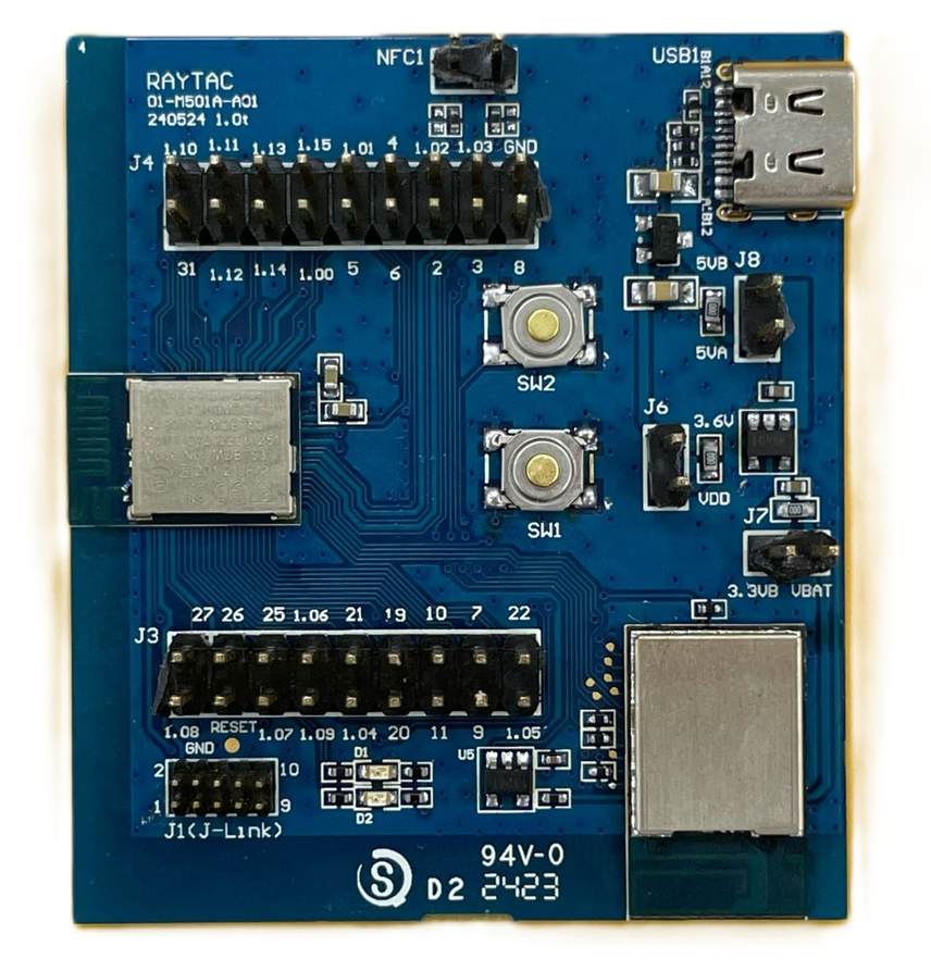
2. 1x Raytac AN54LQ-DB-15
3. 1x IDC Ribbon wire
4. 2x USB-C connector wires (for powering the kit up)
Note: Using Nordic nRF54L15DK / nRF54L15PDK as debugging tool and Raytac Demo board-AN54LQ-DB-15 as simulated carrier board(main board) to proceed the program of nRF54L15 for code compiling and development.


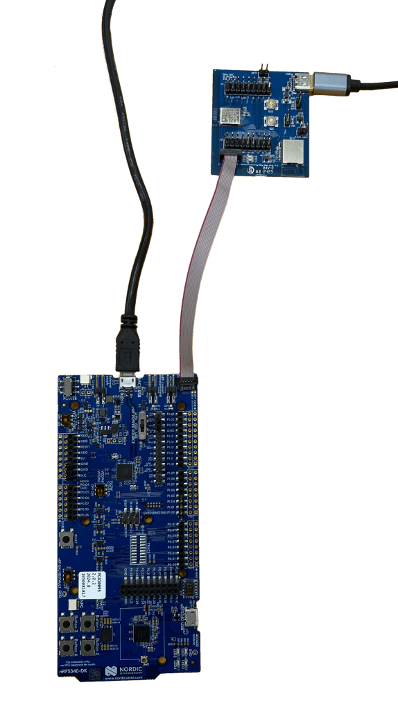
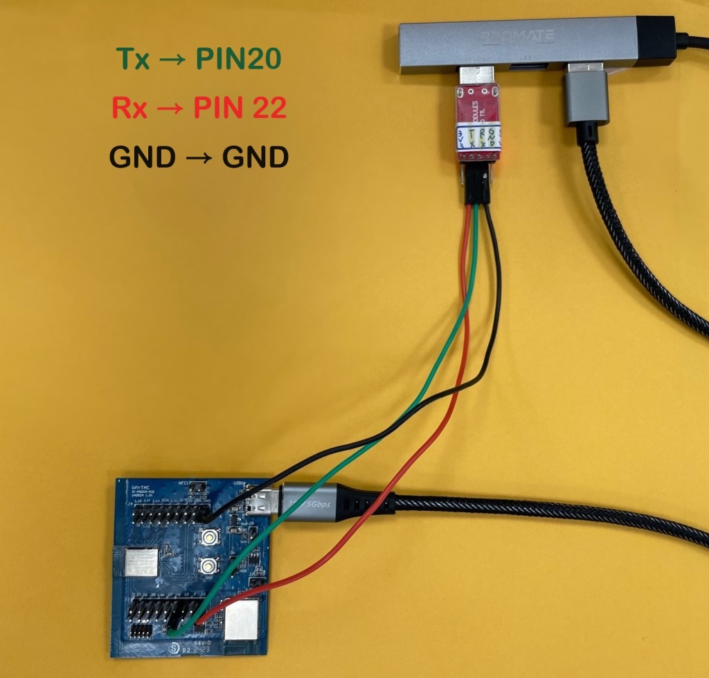
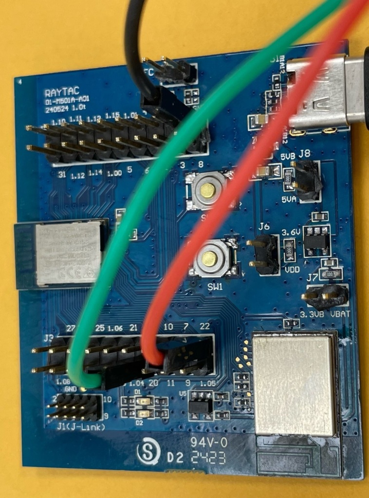
Step 1 —- Connected NRF54L15 DK and AN54LQ-DB-15 by IDC Ribbon wire
Step 2 —- Powering on both NRF54L15 DK and AN54LQ-DB-15 by USB-C connector
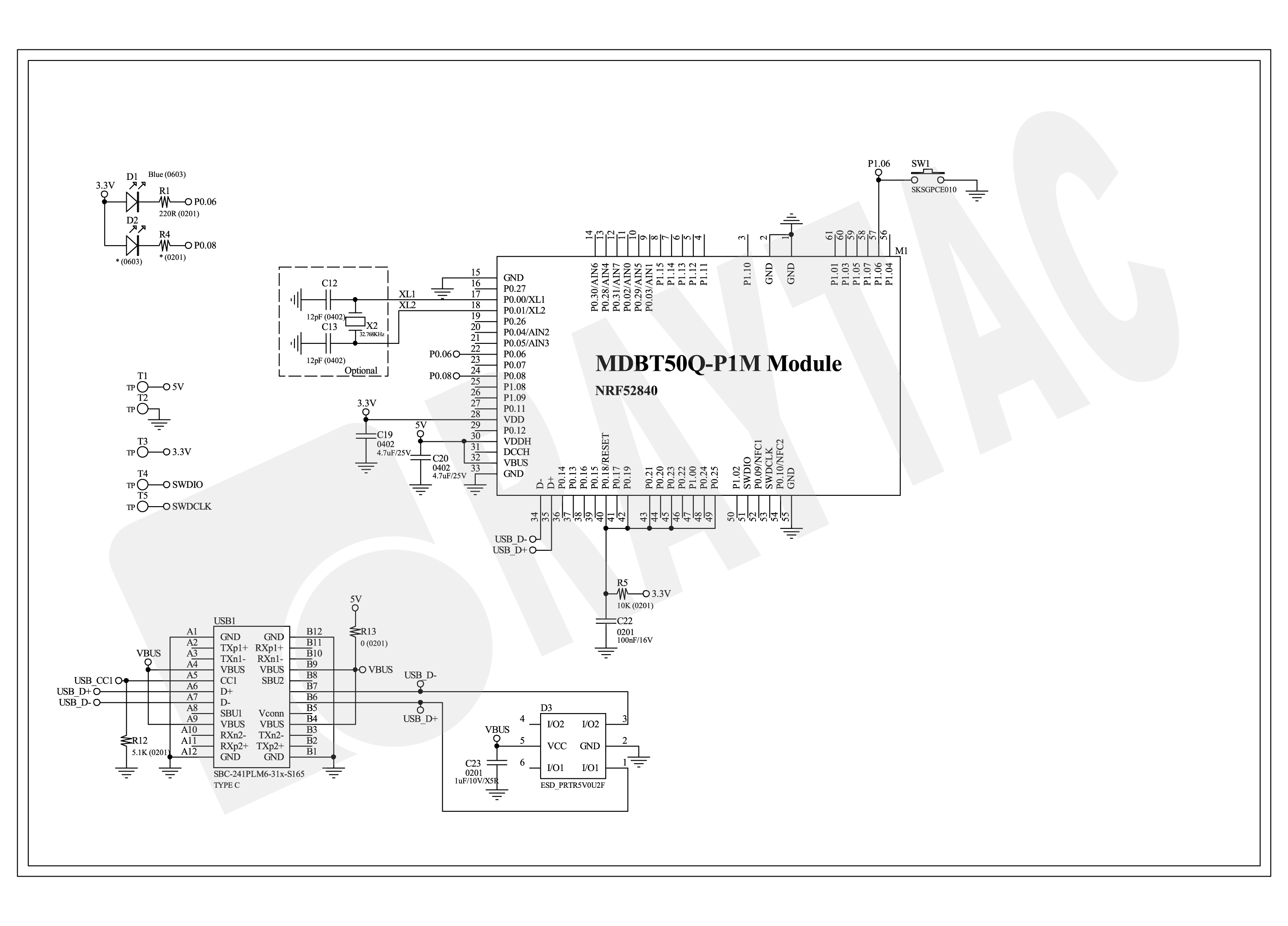
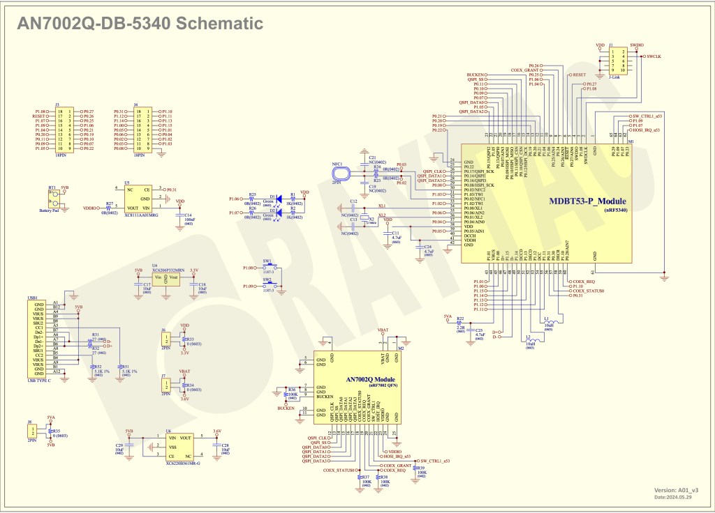
<< Schematic of AN54LQ-DB-15(Updated on 21-Jan-2025) >> (Click on the picture to zoom in)

Software Kits Resource & Preparation
Download nRF Connect For Desktop (Please Click Me)
Download nRF Command Line Tools (Please Click Me)
Preparation
1. Prepared with the latest version of nRF Connect for Desktop and Select version Windows 64-bit – 5.1.0
2. Prepared with the latest version of nRF Command Line Tools and Select version Windows x86 64-10.24.2
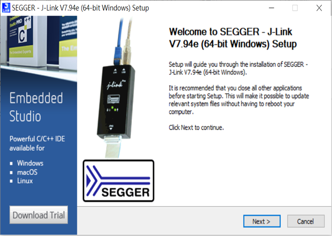
**Note: SEGGER J-LINK Upgrade message might pop up while you’re doing above download.
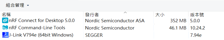
3. Locate all the necessary kits for programming in PC (Check Software/Application list)

Get started with building your program
Intro: The development tool of nRF Connect SDK(NCS) equipped with free VS (Visual Studio) Code IDE for firmware compile and programming.
Note: it is highly recommended to apply NCS 2.8.0 for advanced features of nRF54L15.
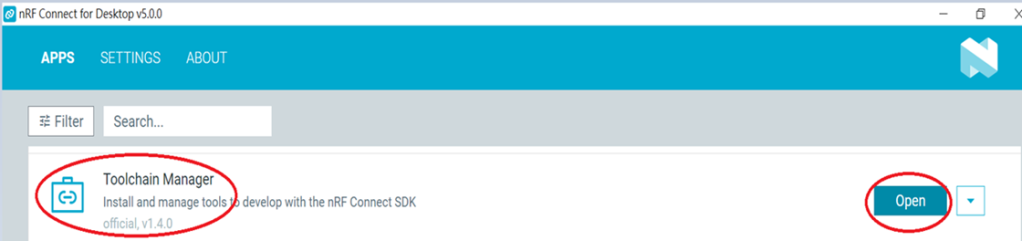
Step 1 —- Activate your “nRF Connect for Desktop” >> “Toolchain Manager” >> “Open” >> “Install”

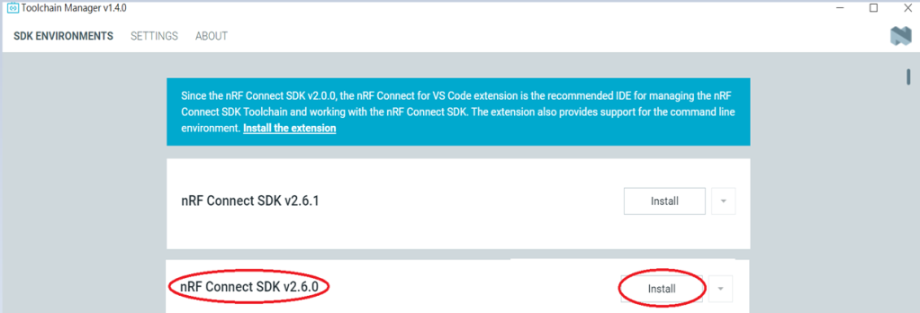
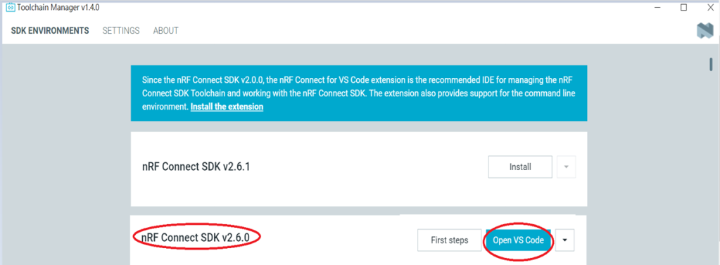
Step 2 —- You will find multiple options of NCS V x.x.x in the tool, we’re using NCS v2.8.0 as example to run sample code of nRF54L15.

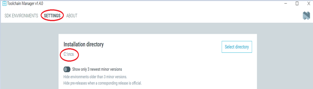
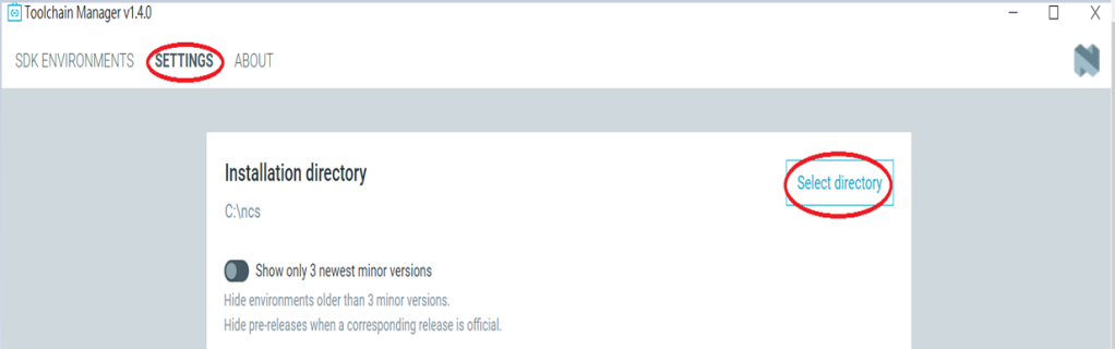
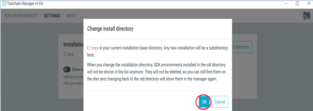
Step 3 —- Make sure the NCS v2.8.0 is installed at same directory with compiling system. (the root of Open VS Code) (This is using C:\ncs as example.)

In case to organize the files, do “Select directory’” and “Confirm”.


Step 4 —- After nRF Connect SDK v2.8.0 Download ready , go “Open VS Code”.

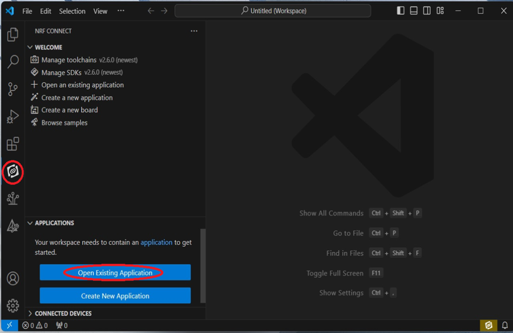
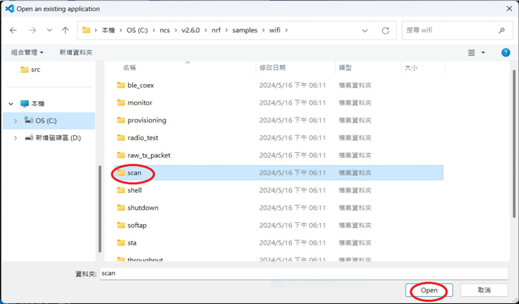
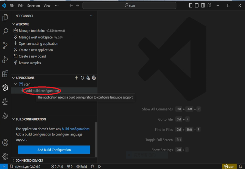
Step 5 —- Go “Open Existing Application” , and activate example code: Bluetooth > peripheral_uart


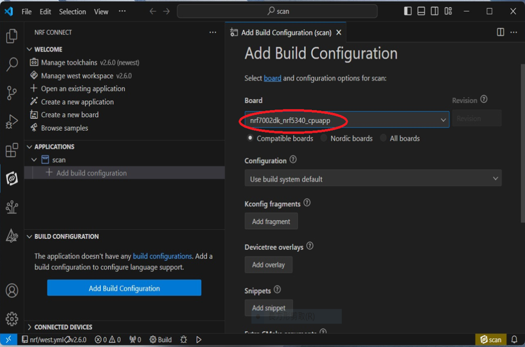
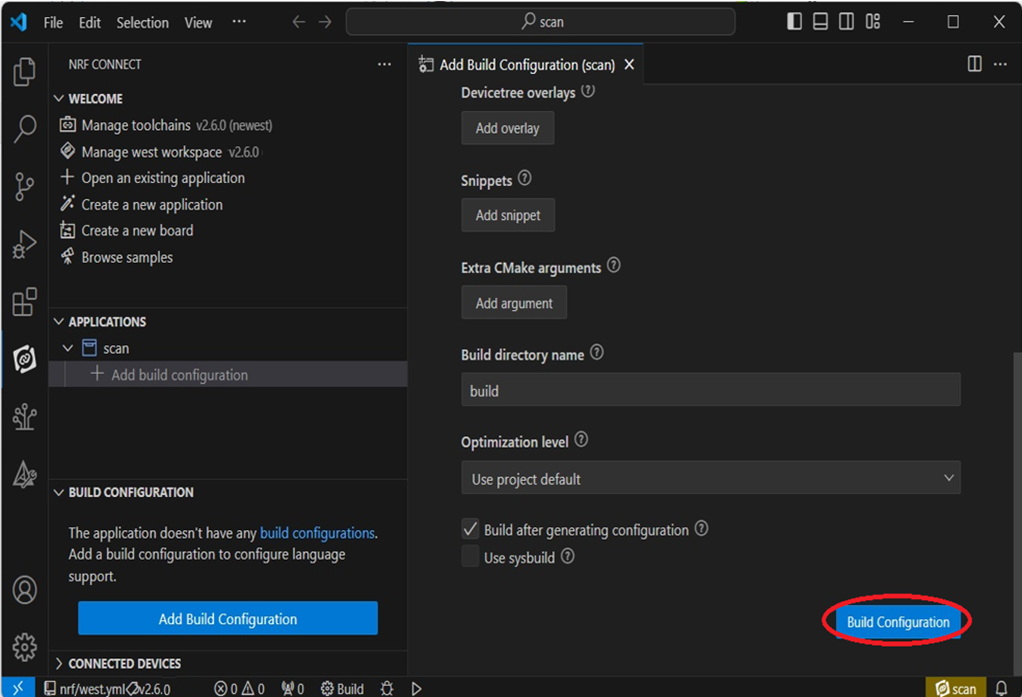
Step 6 —- Moving to program build & compiling by selecting dev kit: nrf54l15dk/nrf54l15/cpuapp


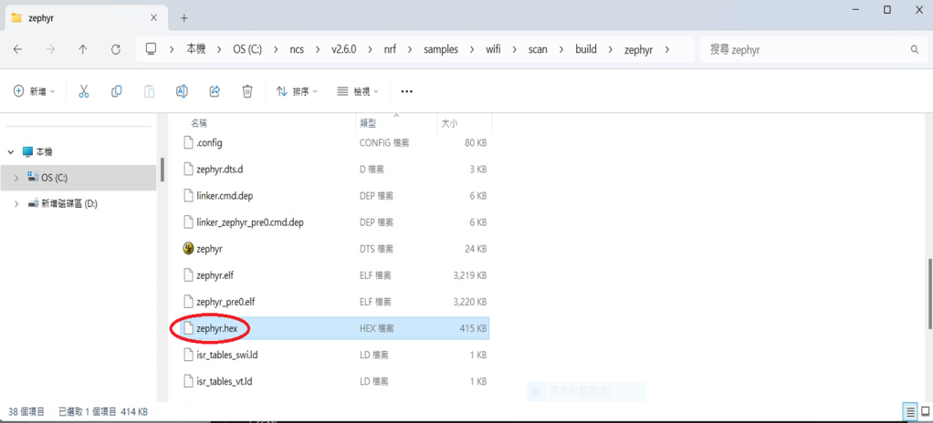
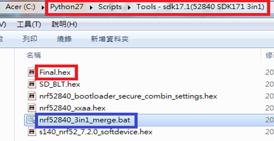
Step 7 —- You will get a .hex file after the above programming compiling process.

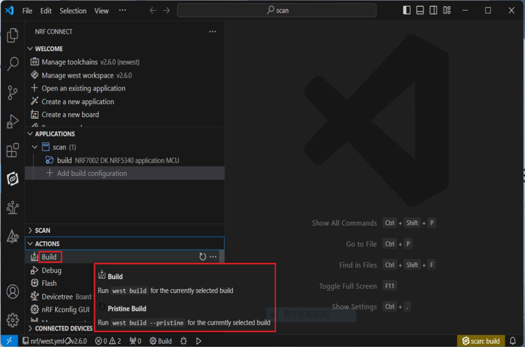
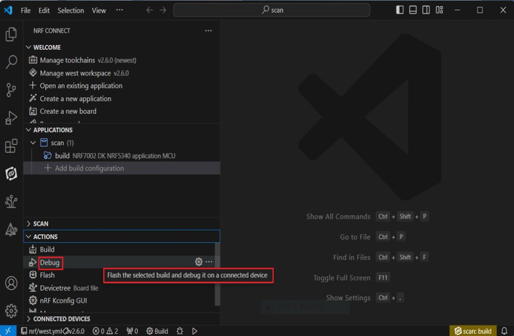
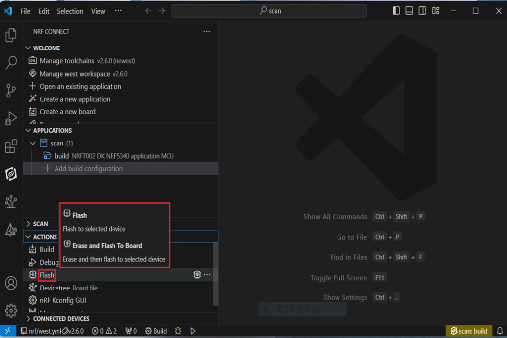
Step 8 —- Functions are available for during the code compiling process under “ACTIONS” in VS Code IDE
<< Build >>

<< Debug >>

<< Flash >>

Firmware Programming
It is feasible to do the firmware programming using nRFConnect SDK (NCS) tool.
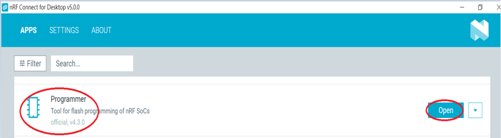
Developer may use “Programmer” to do the firmware flashing with the candidate .hex file.
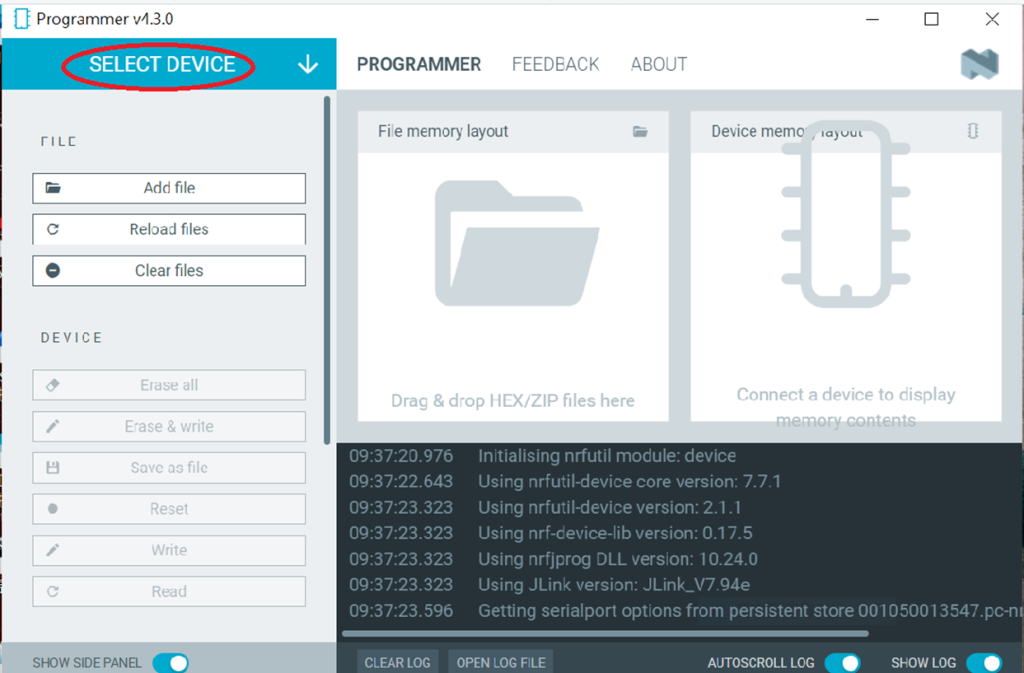
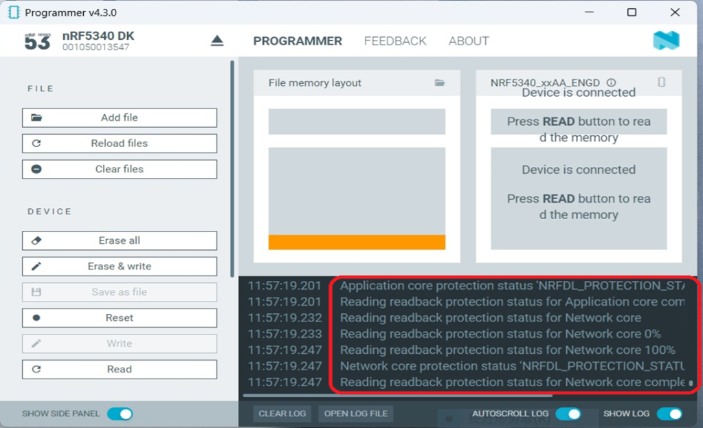
Step 1 —- Execute nRF Connect for Desktop >> Programmer >> Open

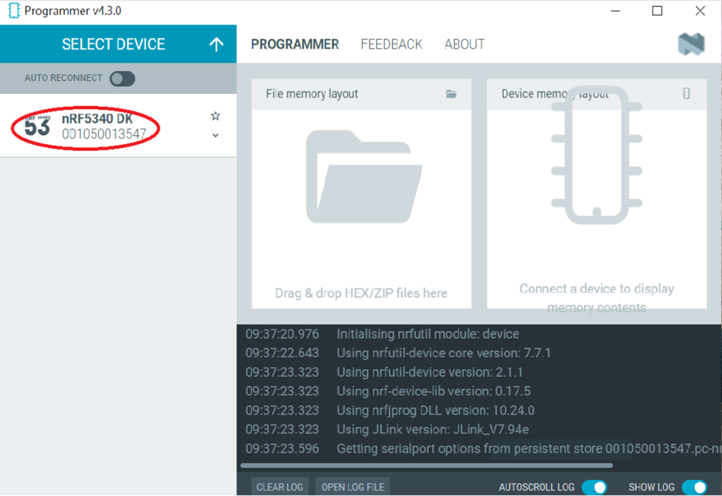
“Select Device”

Select ”nRF54L15 DK”

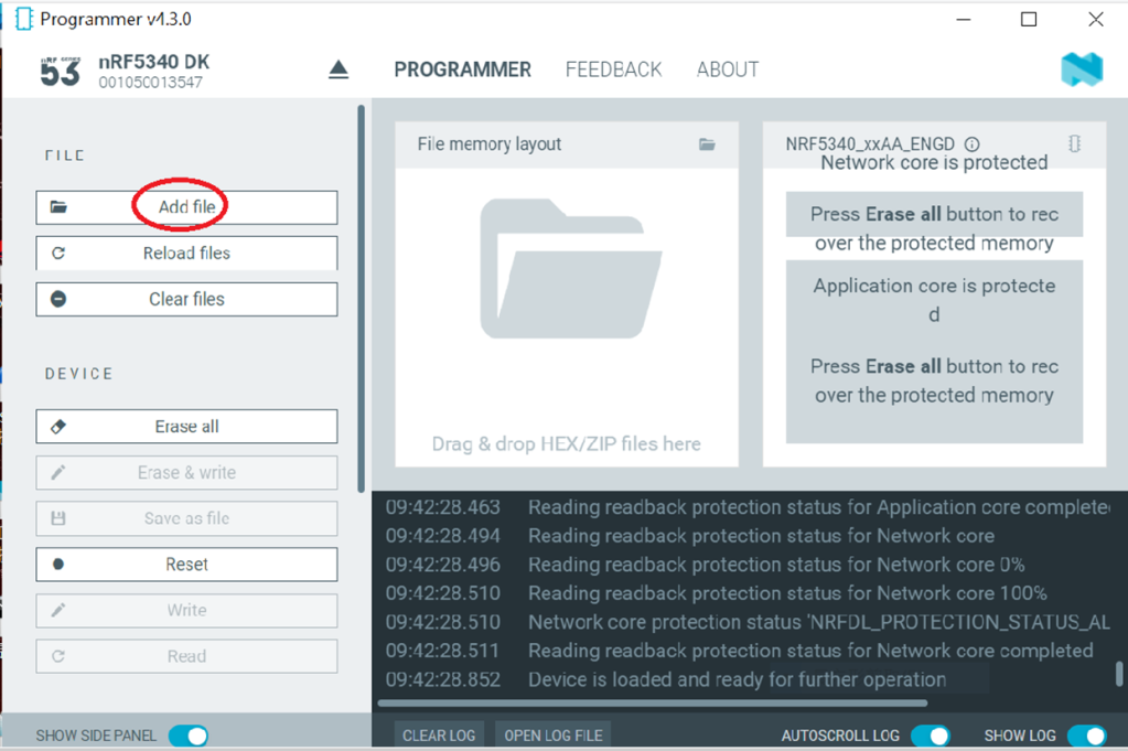
“Add File”

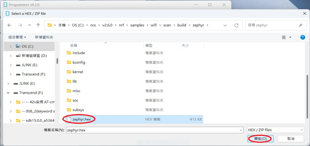
Step 2 —- Select the candidate .hex file


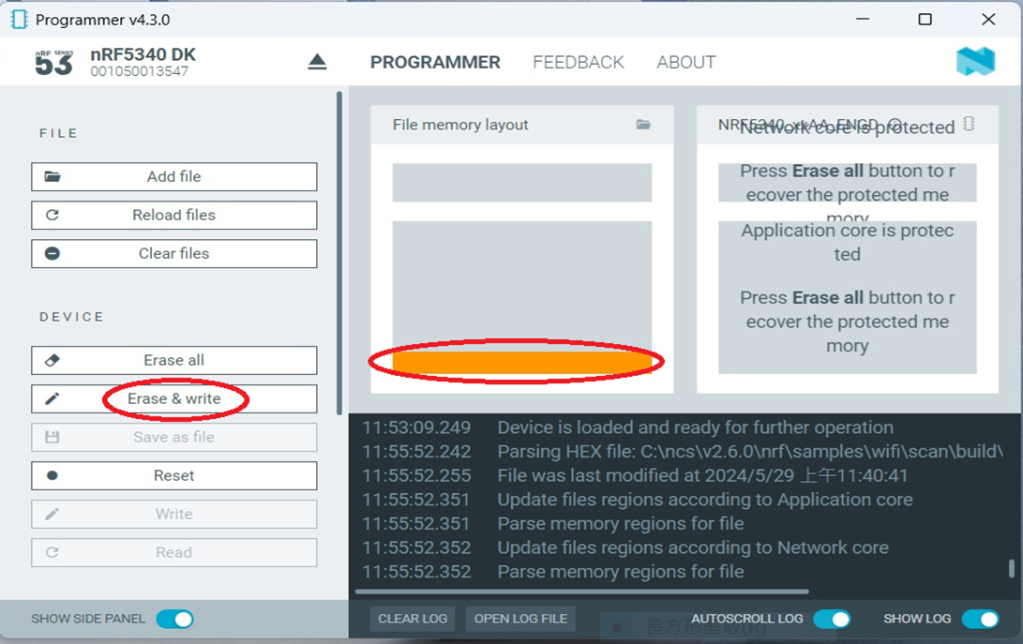
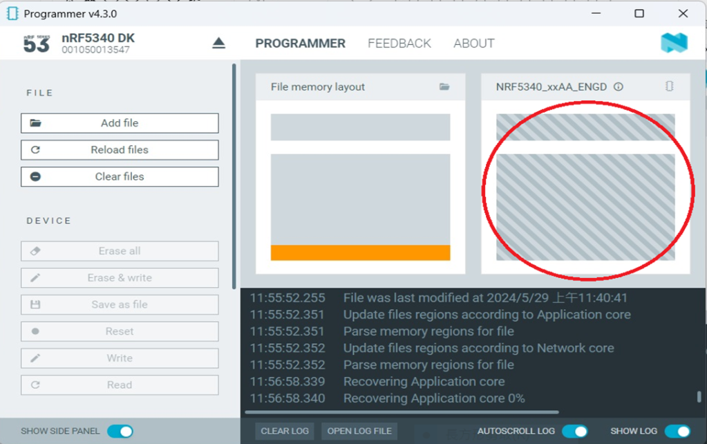
Select “Erase & Write”

It indicates the programming process is on the way↓

The firmware programming process is done after seeing “Completed” in system Log field.

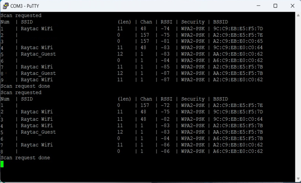
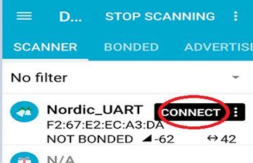
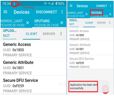
Step 3 —- Use the mobile App to make sure the Bluetooth broadcasting is functioning after the firmware flashing process is successfully done to the module.

D. Channel Sounding Preview
What is Channel Sounding? —- Advance the “Find My” feature into next level accuracy
Have you ever concerned about the distance accuracy when you’re using RSSI to get the distance between devices and to evaluate the transmission distance with legacy Bluetooth module?
Nordic NRF54 solution has taken us into next level with Channel Sounding feature that achieves the “centimeter-level” distance accuracy. Early implement achieves 10-20cm in the record.

How does Bluetooth Channel Sounding work?
Bluetooth Channel Sounding implemented with Phased-Based Ranging (PBR) & Round-trip time (RTT)(the concept idea of TOF time of flight) algorithm to achieve a higher precision of measuring distance between 2 devices.
Phased-Based Ranging (PBR):
Signal has been sent between initiator and reflector with multiple frequency to increase measuring accuracy.

Round-trip time (RTT): It’s the concept of utilizing TOA (Time of arrival). Using TOD(Time of departure) & TOA to measure the timing during the packet transmission between devices.

Potential applications:
Personal item finding
Secure access control
Smart lock system
Digital Key
Asset Tracking
Reference:
Bluetooth Channel Sounding
nRF54L15 DK hardware
nRF Connect SDK Documentation
Nordic Dev Zone forum
AN54LQ-15 Module series
Edited by Business Development Manager: Ms. Jocelyn Tsai
Technical guidance provided by R&D Manager: Mr. MW Lee & Mr. Stanley Huang
Raytac Corporation 勁達國際電子股份有限公司
A Bluetooth, Wi-Fi, and LoRa Module Maker based on
Nordic nRF54; nRF53: nRF52; nRF51; nRF7002
Semtech Specification: SX1262
Bluetooth Specification: BT6 ; BT5.4 ; BT5.3 ; BT5.2.
Wi-Fi Specification: Wi-Fi 6
LoRa Specification: LoRaWAN
All products are FCC/IC/CE/Telec/KC/RCM/SRRC/NCC/WPC Pre-Certified.
http://www.raytac.com
email: sales@raytac.com
Tel: +886-2-3234-0208