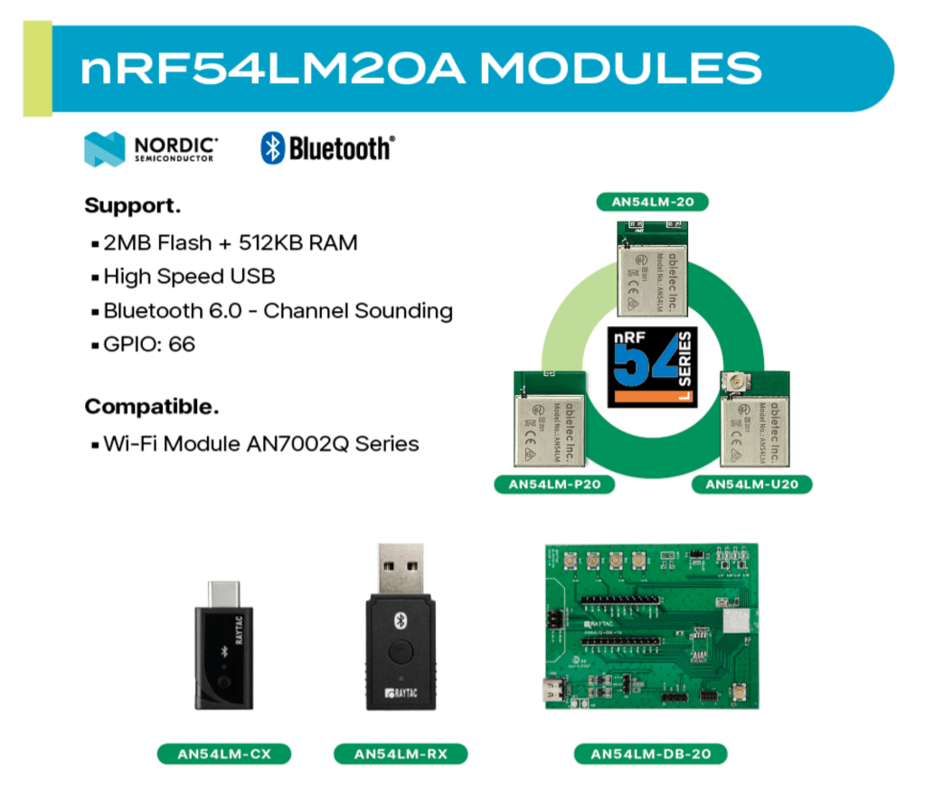
Raytac Group, a worldwide leader in wireless modules, wireless solutions, and a Nordic-recommended third-party module manufacturer, announces the upcoming release of the AN54LM series modules, built on Nordic’s nRF54LM20A/nRF54LM20B SoC.
The series comes in a compact form factor of 9.9 x 13.3 x 2.0 mm (0.39 × 0.52 × 0.08 inches) and offers 3 antenna variants:
The Max output power is +8 dBm and data rates up to 4 Mbps for low-latency applications.
Powered by the nRF54LM20A/B, AN54LM features a high-end dual-core architecture (Arm Cortex-M33 + RISC-V) with up to 2 MB Flash and 512 KB RAM, enabling complex, memory-intensive applications.
In addition to its multi-protocol support, AN54LM series is compatible with the AN7002Q series Wi-Fi modules(nRF7002 solution) to enable Wi-Fi expansions. Know more about the AN7002Q series here.
On the security side, AN54LM series’ hardware and firmware align with EU Cyber Resilience Act (CRA) security principles, helping ensure trusted device operation and lifecycle security.
Alongside modules, Raytac is also working on developing a complete ecosystem, including evaluation boards(Dev Kits) and USB dongles, providing a practical pathway to faster time-to-market for embedded engineers.
“The AN54LM series represents Raytac’s/abietec’s continued commitment to delivering high-quality wireless modules based on Nordic’s solutions." “By combining advanced processing capabilities, multi-protocol support, and a comprehensive development ecosystem, we aim to help all engineers innovate and reduce time-to-market.” — Lyon Liu, CEO, Raytac Group.
Raytac Group, together with Raytac Corporation (USA) and abietec Inc., will exhibit at Embedded World 2026, taking place March 10–12, 2026, at the Nürnberg Convention Center, Germany.
Visit us at Hall 3, Booth 3-426 to discover how Raytac is driving the future of wireless connectivity — from ultra-low-power Bluetooth® modules to advanced Wi-Fi and system-level solutions.
At the show, Raytac will showcase:
Announcement on our AN54LM series: NordicSemi nRF54LM20A modules and dongles that powers up the IoT market with lower power consumption and High speed USB. (Product link click me)
New Nordic nRF54L15 & 10 & 05 series modules: AN54LQ and AN54LV, built for Bluetooth 6.0 with ultra-low power, strong RF performance, coming up with 4 form factors and 7 antenna types
New Wi-Fi + BLE dongle based on the Nordic nRF7002 and nRF5340 solutions
live demos from our partners’ applications
Channel Sounding demo showcasing enhanced ranging accuracy and RF performance
How Raytac’s ecosystem and design partners help you accelerate product development.
abietec Inc. will showcase:
Bluetooth + Wi-Fi combo modules powered by Infineon CYW55912 chipset
Comprehensive OEM/ODM design services supporting a wide range of wireless applications.
Stop by our booth to see live demos, discuss your next project with our engineers, and learn how Raytac and abietec can help bring your wireless ideas to life.
We’re waiting for you at: Embedded World 2026 📍 Nürnberg Convention Center, Germany 📅 March 10–12, 2026 📌 Hall 3, Booth 3-426
Let Raytac and abietec power your next innovation: from concept to connected reality!
Edited by Business Development Manager: Tony Yin
Raytac Corporation 勁達國際電子股份有限公司 / Raytac Corporation (USA) / abietec Inc. A Bluetooth, Wi-Fi, and LoRa Module Maker/ODM & OEM Manufacturer based on Nordic nRF54; nRF53: nRF52; nRF51; nRF7002 Infineon: CYW55912 NXP: RW61 Series Semtech Specification: SX1262
[New Taipei City, Taiwan – January 12, 2026] Raytac Corporation, a global leading supplier of Bluetooth, Wi-Fi, and wireless modules, announces a strategic partnership with Acal BFi(Website link) to strengthen wireless connectivity support for customers across Europe. Through this collaboration, Raytac’s portfolio of pre-certified Bluetooth® Low Energy, Wi-Fi, and Wi-Fi + Bluetooth modules will be supported by Acal BFi’s local application engineering and design-in expertise.
Raytac specializes in short-range RF connectivity, delivering production-ready wireless modules optimized for low power consumption, RF robustness, and fast system integration. Additionally, Raytac focuses on simplifying wireless design while ensuring stable performance across demanding industrial, medical, and IoT environments.
Raytac’s module portfolio includes ultra-low-power Bluetooth LE modules, Wi-Fi modules, and versatile Wi-Fi + Bluetooth combo solutions designed for reliable radio coexistence and long-term availability. All Raytac modules are pre-certified to major global regulatory standards, including CE, FCC, IC, UKCA, TELEC, KC, RCM, SRRC, NCC, and WPC, enabling customers to significantly reduce certification time and compliance risk.
“Great ideas deserve great hardware,” said Lyon Liu, CEO, Raytac. “Our mission is to remove complexity from wireless design. Together with Acal BFi, we can now support customers not only with modules, but with the integration expertise to make sure those modules perform in the real world – in metal housings, in noisy RF environments, in medical devices, in smart sensors, wherever reliability matters.”
“Bluetooth and Wi-Fi connectivity is now a core requirement in almost every market we serve – from smart infrastructure and industrial automation to healthcare and sensing,” said Matthias Beuther, Business Development Manager, Acal BFi. “By partnering with Raytac, we are adding a powerful and proven wireless platform to our portfolio. The combination of Raytac’s module technology and our application engineering expertise gives our customers a faster, lower-risk path to market.”
By working closely with Acal BFi’s IoT & Wireless Technology Centre, customers gain access to local technical support covering antenna selection and tuning, power optimization, enclosure considerations, and coexistence validation. This partnership enables a more predictable, minimal-risk path from prototype to volume production for high-reliability wireless products deployed in real-world environments.
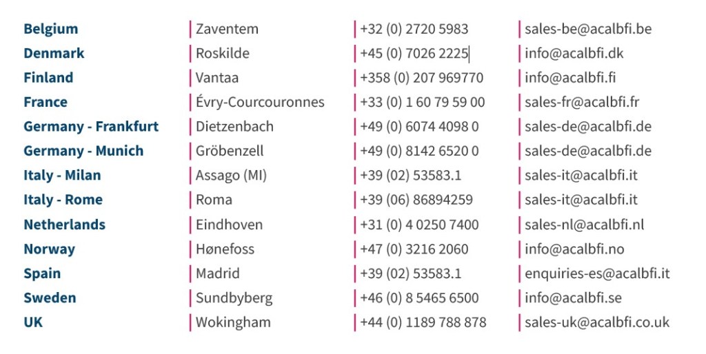
For inquires, please contact the below Acal BFi regional offices:
Edited by Business Development Manager: Tony Yin
Raytac Corporation 勁達國際電子股份有限公司 / Raytac Corporation (USA) / abietec Inc. A Bluetooth, Wi-Fi, and LoRa Module Maker/ODM & OEM Manufacturer based on Nordic nRF54; nRF53: nRF52; nRF51; nRF7002 Semtech Specification: SX1262
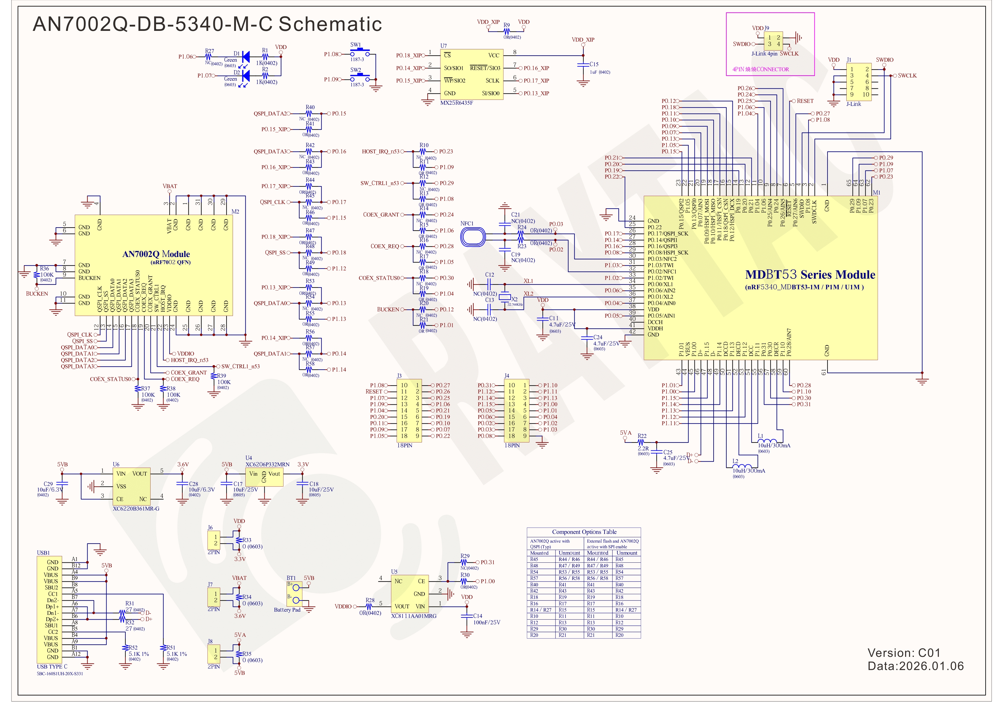
Raytac has advanced the dev kit version of bundle offer – WIFI+BLE: AN7002Q-DB- 5340-M with an on-board flash memory(MX25R64) to create easy evaluation for Wi-Fi project developments.
[January 2026 Update] In this article, we will talk about: Project WITH External Flash MX25R64(8MB) applied – Connecting through SPI between nRF5340 module: MDBT53-1M(BLE) & nRF7002 module: AN7002Q(WIFI) – Connecting through QSPI (XIP) between MDBT53-1M and external memory MX25R64
Table of Content———————————————————————————————————
Hardware Set Up A. Project WITHOUT External Flash MX25R64 needed B. Project WITH External Flash MX25R64 needed
Software Resources & Preparations
Firmware Build & Compile A. Project WITHOUT External Flash MX25R64 needed B. Project WITH External Flash MX25R64 needed
Note: Pease make sure to have both “Nordic nRF5340-DK” and “AN7002Q-DB-5340-M”connected and running during the WIFI+BLE (nRF7002+nRF5340) project development.
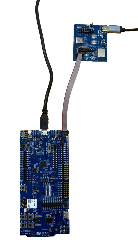
Hardware Network: IDC Ribbon Wire(J-Link Cable): Connect nRF5340-DK to AN7002Q-DB-5340-M USB Wire –Type C USB: Power supply to AN7002Q-DB-5340-M through USB TYPE-C USB Wire-Micro USB: Power supply to nRF5340-DK through Micro USB
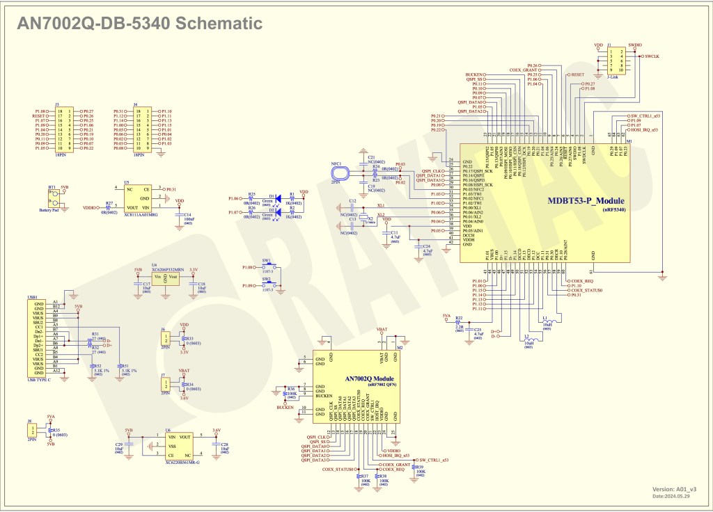
Schematic diagram of AN7002Q-DB-5340-M can be referenced for design as follows. *nRF7002 module <- SPI -> nRF5340 module *MX256R NOR Flahs <-QSPI-> nRF7002 module (Click on the image to zoom in.)
!! Important Note:!! The circuit of SW1(p1.08)/SW2(p1.09)/LED1(p1.06) on AN7002Q-DB-5340-M is NOT COMPATIBLE to Nordic WI-FI Control Pin of swctrl1(p1.08)/host_irq(p1.09)/grant(p1.06). In this case, if you’re working with external flash MX25R64 for the WIFI project, Please avoid pin SW1/SW2/LED1 usage while LED2(p1.07) remains available as normal usage. For the PCB design of end product/end device(mounted with AN7002Q & MDBT53 modules), the switch & LED should be configured to be: SW1(p0.23)/SW2(p0.24)/LED1(p0.28).
Step 1: Prepared with the latest version of nRF Connect for Desktop, using Windows 64-bit – 5.2.0 Step 2: Prepared with the latest version of Command Line Tools, using Windows X86 64 – 10.24.2
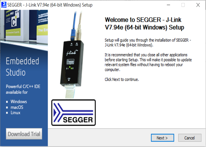
**Note: SEGGER J-LINK Upgrade message might pop up while you’re doing above downloads.
Step 3: Locate all the necessary kits for programming in PC
3. Firmware Build & Compile After you download and set up nRFConnect SDK (NCS), you will be able to apply free VS (Visual Studio) Code IDE as firmware programming tool.
The below example uses NCS v3.1.1 and runs the program under: C:\ncs
Step 1: Start with a Wi-Fi Scan project and run the program under: C:\ncs\v3.1.1\raytac <<Create a new application and Copy a sample>>
Step 2: Select SDK v3.1.1 to copy the sample
Step 3: Select example by entering keyword: wifi scan(Wi-Fi Scan)
Step 4: Enter application location: C:\ncs\v3.1.1\raytac and name the project as: wifi_scan_uart_dfu
Step 5: Open an existing application and find the registered project: wifi_scan_uart_dfu
Step 6: How to activate the Devicetree setting of Wi-Fi nRF7002 and Create file:nrf5340dk_nrf5340_cpuapp.overlay Code example is as follows: / { chosen { aliases { /delete-node/ leds; /delete-node/ buttons; }; };
Step 7: It is required to do MCUBoot before working with DFU using External Flash Please do the code configuration in sysbuild.conf as following reference code.
SB_CONFIG_BOOTLOADER_MCUBOOT=y # DFU with UART SB_CONFIG_MCUBOOT_MODE_SINGLE_APP=n
# DFU with external flash SB_CONFIG_PM_EXTERNAL_FLASH_MCUBOOT_SECONDARY=y
Step 8: It is required to doMCUMGR before working with DFU over UART Please do the code configuration in prj.conf as following reference code.
# Enable QSPI driver for Application CONFIG_NORDIC_QSPI_NOR=y
# Enable mcumgr DFU in application CONFIG_MCUMGR=y CONFIG_NET_BUF=y CONFIG_ZCBOR=y CONFIG_CRC=y
# Enable mcumgr management for both OS and Images CONFIG_MCUMGR_GRP_OS=y CONFIG_MCUMGR_GRP_IMG=y CONFIG_FLASH=y CONFIG_IMG_MANAGER=y CONFIG_STREAM_FLASH=y CONFIG_FLASH_MAP=y
# Configure MCUMGR transport to UART CONFIG_MCUMGR_TRANSPORT_UART=y CONFIG_BASE64=y
Step 9: Add with MCUBoot setting , and create a root for sysbuild ; Build with file mucboot.overlay & file mcuboot.conf
9A. To the File: mucboot.overlay &mx25r64 { status = “okay"; };
Step 10: Create a VERSION file by referencing the following code when testing DFU over UART. VERSION_MAJOR = 99 VERSION_MINOR = 0 PATCHLEVEL = 0 VERSION_TWEAK = 0 EXTRAVERSION =
Step 14: Generate a Merged.hex file after compiling the program
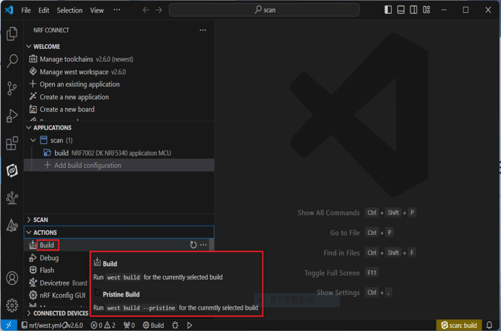
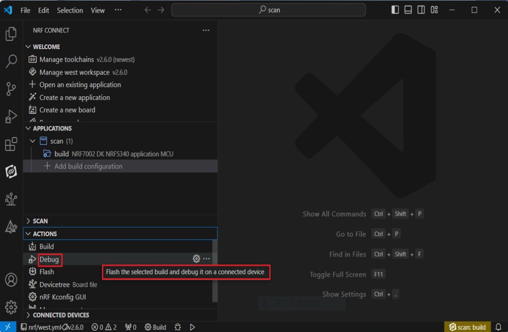
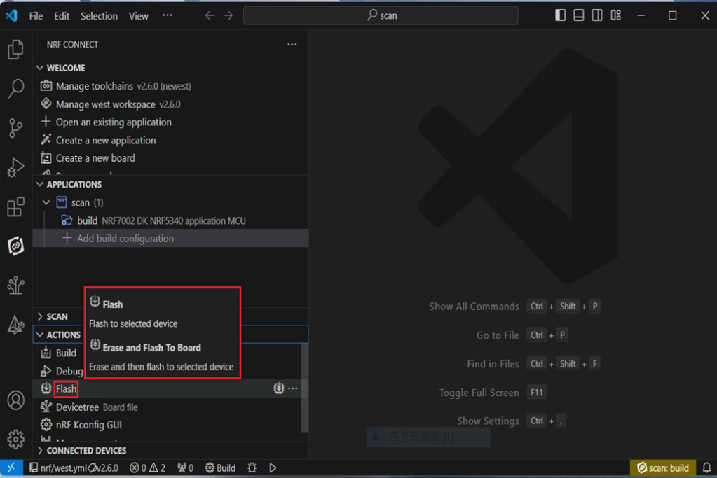
Step15: You can choose Build/Debug/Flash under ACTIONS during development << Build >>
<< Debug >>
<< Flash >>
Step 16: Go to ACTIONS >> Memory report to check the memory partitions.
Now you can see partitions available in the system. mcu_secondary has already been located in MX25R64 flash memory.
4. Test/Validate DFU Process & WIFI SCAN After the firmware programmed to MDBT53 module on board, we use the USB to UART adaptor board for connecting AN7002Q-DB-5340-M through: A. MCUMGR UART to PC and through: B. WiFi Scan UART to PC respectively. Note: We suggest you finish connecting A. and B. before running tests.
Now we can run the tests.
A. DFU over UART – Using AuTerm Program 1. We can locate Image version=V99.0.0 under the current VERSION file
It also indicates Image version: 99.0.0 in MCUmgr-Slot 0.
2. Try to modify the file version from V99 to V100 under VERSION file: VERSION_MAJOR = 100
VERSION_MINOR = 0
PATCHLEVEL = 0
VERSION_TWEAK = 0
EXTRAVERSION =
And go with “Pristine Build”
3. We’re about to run DFU over UART , Please DO NOT do “Flash” or “Erase”.
Proceed with “Force reboot”
4. It’s now Version 100.0.0 in Slot 0 under MCUgr ⭢ DFU over UART successfully done!
Before it was Version 99.0.0 in Slot 1 under MCUgr.
B. WIFI SCAN – PuTTY Console WIFI SCAN credentials can be located under PC Console – PuTTY.
Bluetooth Channel Sounding adds a new dimension to wireless connectivity by combining secure data transfer with the low‑power, low‑cost Bluetooth technology already trusted worldwide — now extended to deliver precise location awareness. This evolution means IoT devices can gain both communication and ranging capabilities in a single, efficient platform. With tens of centimeter distance accuracy, Channel Sounding enables practical new use cases such as secure access, proximity‑based services, indoor navigation, and ‘Find My’ functionality.
Android 16 now supports Channel Sounding APIs, making it possible for developers to access this capability directly on flagship devices like the Pixel 10. With anticipated pervasive adoption across the mobile ecosystem, Channel Sounding is positioned to scale broadly and become a standard feature for IoT applications.
The onceLabs demo was reported as the first of its kind in August, gaining notability on LinkedIn(Post link) — and is now being shown for the first time in a public venue. onceLabs’ free BLE Hero app(Download Link) is a sniffer, analyzer, and development tool, available in app stores, and can be seen in action during the live demo. The Android version has been updated to capture and display Channel Sounding data, giving developers clear insight into ranging accuracy and system performance. Since 2018, Raytac and onceLabs have collaborated to bring new Bluetooth capabilities from specification to market‑ready solutions. Raytac’s proven hardware platforms and onceLabs’ application‑layer software expertise combine to accelerate adoption of emerging standards, showing how partnership can translate advanced technology into product‑ready functionality.
QR code on the left: watch the Channel Sounding Live Demo; QR code on the right: download the BLE Hero app on Google Play.
“Our collaboration with onceLabs has always been about enabling customers to move quickly and confidently with the latest Bluetooth technology,” said Lyon Liu, CEO of Raytac Corporation. “This live demo of Channel Sounding is another example of how our partnership delivers not just modules, but complete solutions that inspire new applications.”
Together, Raytac and onceLabs are demonstrating how Bluetooth Channel Sounding can move from specification to practical demonstrations that product companies can act on.
“With Raytac providing the hardware foundation and onceLabs delivering the application software, we continue to support customers in translating new Bluetooth features into real use cases,” said Joseph Bakalor, President and CTO of onceLabs. “Channel Sounding is a perfect example — and with our expertise in Zephyr RTOS, developers can build on open, production‑ready software that scales from prototype to deployment.”
The Raytac + onceLabs demo will be featured in Raytac Booth 5067 at embedded world North America, November 4–6, 2025, at the Anaheim Convention Center. Attendees are invited to visit the booth to see the demo in action and learn how Raytac and onceLabs can support their next wireless product.
About Raytac Raytac Corporation is a leading provider of wireless modules, offering one of the industry’s broadest portfolios of pre‑certified solutions built on Nordic Semiconductor SoCs. With a focus on quality, reliability, and ease of integration, Raytac helps product companies accelerate development and reduce risk when bringing wireless products to market. From consumer devices to industrial applications, Raytac modules are trusted worldwide for their performance, compliance, and long‑term availability. Company website: www.raytac.com
About onceLabs onceLabs delivers custom embedded firmware and mobile application software with a passion for translating client use cases into cloud‑enabled applications that leverage the latest wireless innovations. Known for delivering quality user experiences while optimizing performance and power consumption, onceLabs helps bring products to life through custom software. With design expertise spanning Bluetooth LE, Wi‑Fi, cellular, and other wireless protocols — and a strong engineering foundation in both embedded and mobile software — onceLabs accelerates time‑to‑market through a systems approach to architecture, continuous integration, and real‑world reliability. Company website: www.oncelabs.com
Edited by Business Development Manager: Tony Yin
Raytac Corporation 勁達國際電子股份有限公司 / Raytac Corporation (USA) / abietec Inc. A Bluetooth, Wi-Fi, and LoRa Module Maker/ODM & OEM Manufacturer based on Nordic nRF54; nRF53: nRF52; nRF51; nRF7002 Semtech Specification: SX1262
We are thrilled to announce that Raytac Corporation will be participating in Embedded World 2025 from March 11 to March 13, 2025, at the Nuremberg Exhibition Centre in Germany.
IoT and Wireless technologies such as Bluetooth Low Energy (BLE), Wi-Fi, and LoRa…etc. continue to reshape industries worldwide, that’s why Raytac is at the forefront, providing cutting-edge solutions that accelerate product development. Together with our partner, Nordic Semiconductor, we offer a comprehensive range of modules designed to meet the increasing demands of today’s connected world.
This year, we have exciting innovations to showcase:
Unveiling our new service: Customized OEM/ODM designing for customers.
These are just a few of the groundbreaking solutions we’ll be unveiling. You won’t want to miss the chance to experience these with us!
What to Expect at Our Booth:
Live demonstrations showing how Raytac’s modules can be implemented in multiple industries.
Discover how our modules can reduce development time and costs, making your projects more efficient.
One-on-one consultations with our experts to help you find the right solutions for your needs.
Stop by and visit us at: HALL 3 Booth 3-111 M2M Area
We would love to connect with you and discuss how Raytac can support your next project. Whether you’re an engineer, developer, or business decision-maker, we have something for everyone at Embedded World 2025.
Here are the guidelines for users to implement Secure DFU OTA(over-the-air) while using nRF52832 Solution modules. (Click on link for Raytac nRF52832 module series)
In this article, we will be focusing on Part 1: Bootloader & Application.
Bootloader
Path: ..\nRF5_SDK_16.0.0_98a08e2\examples\dfu\secure_bootloader\pca10040_s132_ble\arm5_no_packs Specifically for nRF52832, programmers need to embed ECC(Elliptic Curve Cryptography) into the bootloader.
Step 1. ’micro_ecc_lib_nrf52.lib’ library can be found in the path below, but we need to boot it up first.
Step 2. Unzip ’micro-ecc-master.zip’ to the below path(create a new “micro-ecc” file first).
Step 3. Run ’gcc-arm-none-eabi-7-2018-q2-update-win32.exe’.
Step 4. Make sure the Environment variables in Win10 are set as below.(Follow the steps 1 to 6)
Step 5. Open DOS → run the “make” command under armgcc path → generate’micro_ecc_lib_nrf52.lib’
Step 6. Add ’micro_ecc_lib_nrf52.lib’ into folder: nRF_micro-ecc
Step 7. An error may occur while building bootloader without a public key: (Shown in red frames in below screenshot)
Step 8. How to generate the public key file in Bootloader? A. Visit DOS at path: ..\Python27\Scripts B. Then execute:
Step 9. Copy the pk[64] code from (public_key.c) into (dfu_public_key.c) (Shown in red frames in below screenshot)
※Note: Make sure to save the 3 generated files: private.pem public_key.c dfu_public_key.c
Step 10. Generate the bootloader file:nrf52832_xxaa_s132.hex after re-compiling the code files.
Application
Path: ..\nRF5_SDK_16.0.0_98a08e2\examples\ble_peripheral\ble_app_uart\pca10040\s132\arm5_no_packs Before building Application code , some amendments need to be made regarding DFU-related settings and code inside Application:
Step 1.Add code in definition in C/C++ : BL_SETTINGS_ACCESS_ONLY NRF_DFU_SVCI_ENABLED NRF_DFU_TRANSPORT_BLE=1 (Total 3 steps definitions need to be set up)
Step 2. Add the 3 paths shown below in C/C++ to make DFU work.
Step 3. Add the .c files inside red frame in (Screenshots 1 & 2) and add the 2 groups of (nRF_DFU & nRF_SVC)(Screenshot 4) under Project(Screenshot 3)
Step 4.Add code into main.c file in Application (..\examples\ble_peripheral\ble_app_uart\main.c) (Please refer to: main.c file at: ..\examples\ble_peripheral\ ble_app_buttonless_dfu)
Step 5. The code of file: sdk_config.h (..\examples\ble_peripheral\ble_app_uart\pca10040\s132\config\sdk_config.h) inside Application needs to be modified.
Step 6. Adjust the IRAM1 value in Target after implementing DFU service: Make sure the IRAM1 Value of *p_app_ram_start is modified from default: 0x20002AD8 0xD528 to 0x20002AE8 0xD518, as shown in the red frame in the bottom right corner. In this case, the program should run/advertise successfully.
Step 7. Create a file of: nrf52832_xxaa.hex after building application code files.
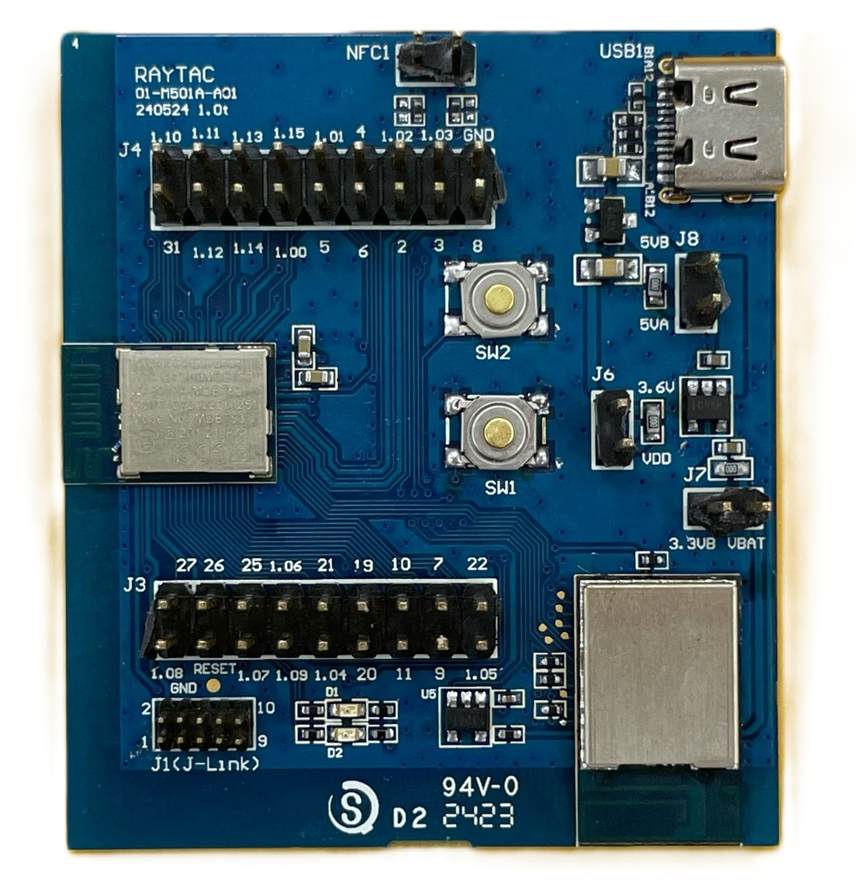
Recently we have received the FAQ: how to write MAC address into the OTP memory of Raytac’s AN7002Q-P Nordic Wi-Fi module? In this article, we’ll get this question explained to give customers a more smooth experience using the AN7002Q-nRF5340 Demo Board(AN7002Q-DB-5340).
Is there an existing Wi-Fi MAC address in the AN7002Q part on the DevKit?
Currently, the AN7002Q module on Raytac’s AN7002Q-DB-5340 board has no Wi-Fi MAC address.
When running Wi-Fi Scan code/Station code/Shell code…etc. on NCS v2.6.0 (and later versions), the AN7002Q module must have a programed Wi-Fi MAC address to function properly.
Therefore, it’s necessary to follow the below process: 1. Program the original Wi-Fi radio test code (..\nrf\samples\wifi\radio_test) into the MDBT53 section, 2. Then write the Wi-Fi MAC address in to the AN7002Q section(nRF7002 IC) via command.
After this, program the original Wi-Fi Scan code/Station code /Shell code … into the 5340, and it will function properly.
**Raytac will assign 2 Wi-Fi MAC addresses(for both 2.4GHz & 5GHz) to every AN7002Q module. *If customers don’t have Wi-Fi MAC addresses for DevKit development yet, please reach out to service@raytac.com
Scenario: Following error occurred when building the SCAN example code, flash it onto the AN7002Q-DB-5340 board, and run the test.
Solution:
When running Wi-Fi scan code on NCS v.2.6.0 or later version, the OTP memory in the AN7002Q module must have a Wi-Fi MAC address programmed in for the Wi-Fi scan functionality to work properly.
(Note: OTP is a One-Time programmable memory, which means the value can only be written once. The customer must aware of this before performing the OTP operation.)
1. Program the original Wi-Fi radio test code (..\nrf\samples\wifi\radio_test) into the MDBT53 section, then manually input and execute the following OTP read command.
wifi_radio_ficr_prog otp_read_params
If you see both MAC0 and MAC1 display a value of 0xFF, as shown in above, it means that you haven’t written the Wi-Fi MAC address into the AN7002Q’s OTP.
2. Manually issue the OTP write command to write the Wi-Fi MAC address into the OTP.
After you complete the above, use the OTP read command in below to check if the Wi-Fi MAC address value was written. The MAC0 and MAC1 should display the value you’ve input from the OTP write command.
wifi_radio_ficr_prog otp_read_params
3. Program the original Wi-Fi SCAN code back into the MDBT53, the Wi-Fi scan functionality should work properly.
To help you quickly get started with Raytac’s AN7002 Nordic WiFi module and nRF5340 module, here’s a simple guide on how to set up the development and programming environment using AN7002Q-nRF5340 Demo Board(AN7002Q-DB-5340)and nRF5340 DK.
This article will cover the 4 sections below: 1. Hardware setup 2. Software Development Kit and Environment setup 3. Programming/Development 4. Flashing/Uploading firmware
1. Hardware Setup 1 x Nordic nRF5340-DK: PCA10095(2.0.0) 1 x Raytac AN7002Q-DB-5340 1 x IDC Cable 1 x USB-Micro USB Cable 1 x USB-Type C USB Cable
*Note: You need to use both the “Nordic nRF5340-DK” and “Raytac AN7002Q-DB-5340 demo board” together for programming and development. *
Steps to connect the hardware:
Connect J-Link on Nordic DK to AN7002Q-DB-5340using IDC Cable
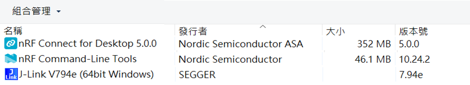
After the installations are completed, you can see the following applications under the:
“Programs and Features" section in the Control Panel.
3. Programming/Development
nRF Connect SDK (NCS) supports development using the free VS (Visual Studio) Code IDE. Here’s how to select and install the NCS SDK version (nRF Connect SDK vx.x.x):
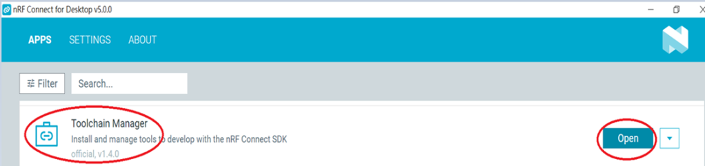
Step1.
Open “nRF Connect for Desktop” → Choose “Toolchain Manager” → then click” Open”
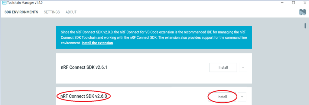
Step2.
You’ll see a list of nRF Connect SDK versions. It’s recommended to install NCS v2.6.0 or later. Here, we use NCS v2.6.0 as an example.
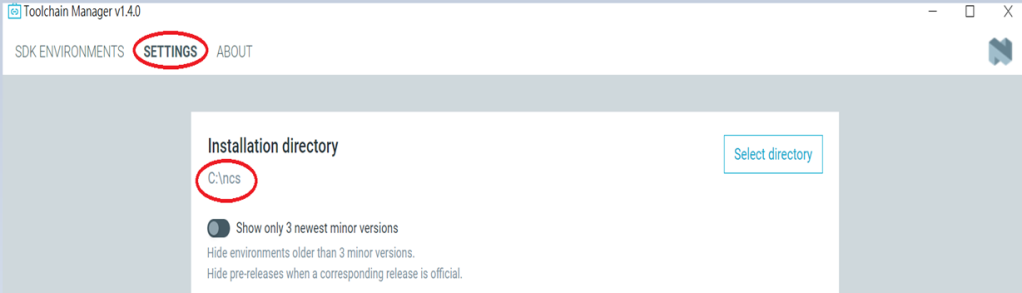
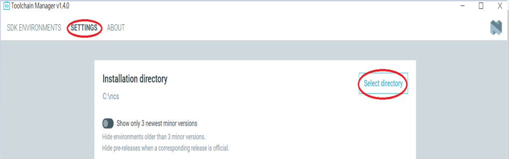
Step3.
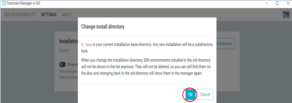
Before installing NCS v2.6.0, confirm the installation path (Default path → C:\ncs).
If you want to change the path, click “Select directory”, and press OK.
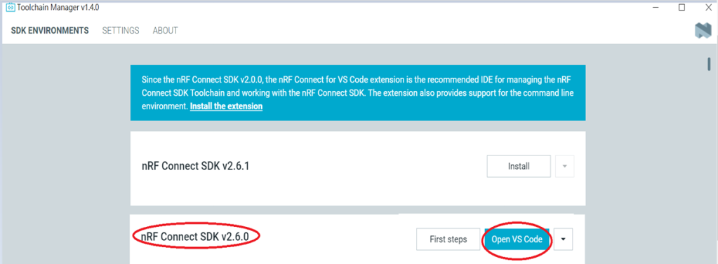
Step4.
After installing the nRFConnect SDK v2.6.0, click “Open VS Code”.
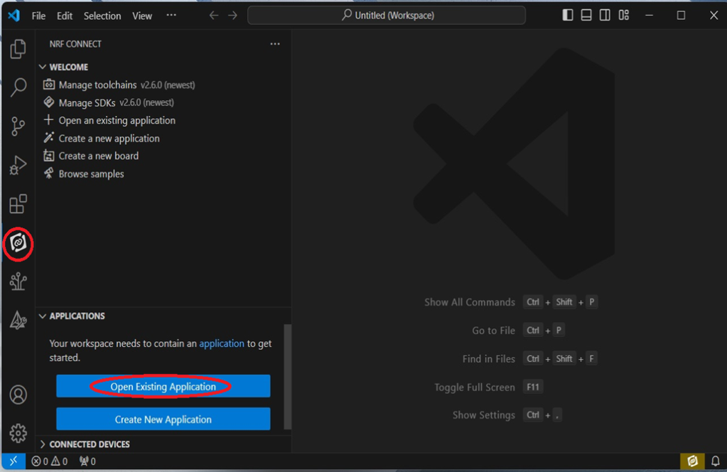
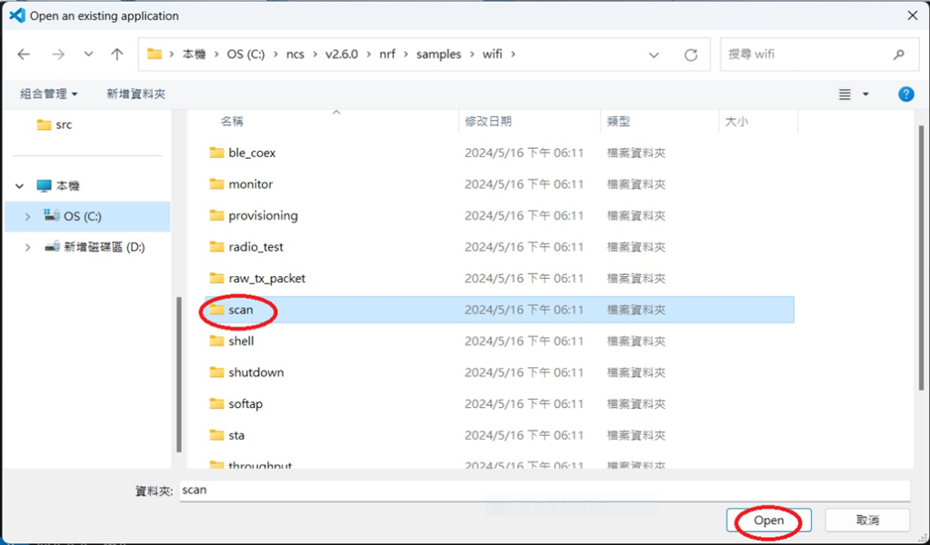
Step5.
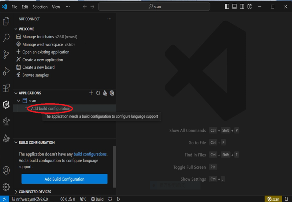
Open the Wi-Fi scan example
Step6.
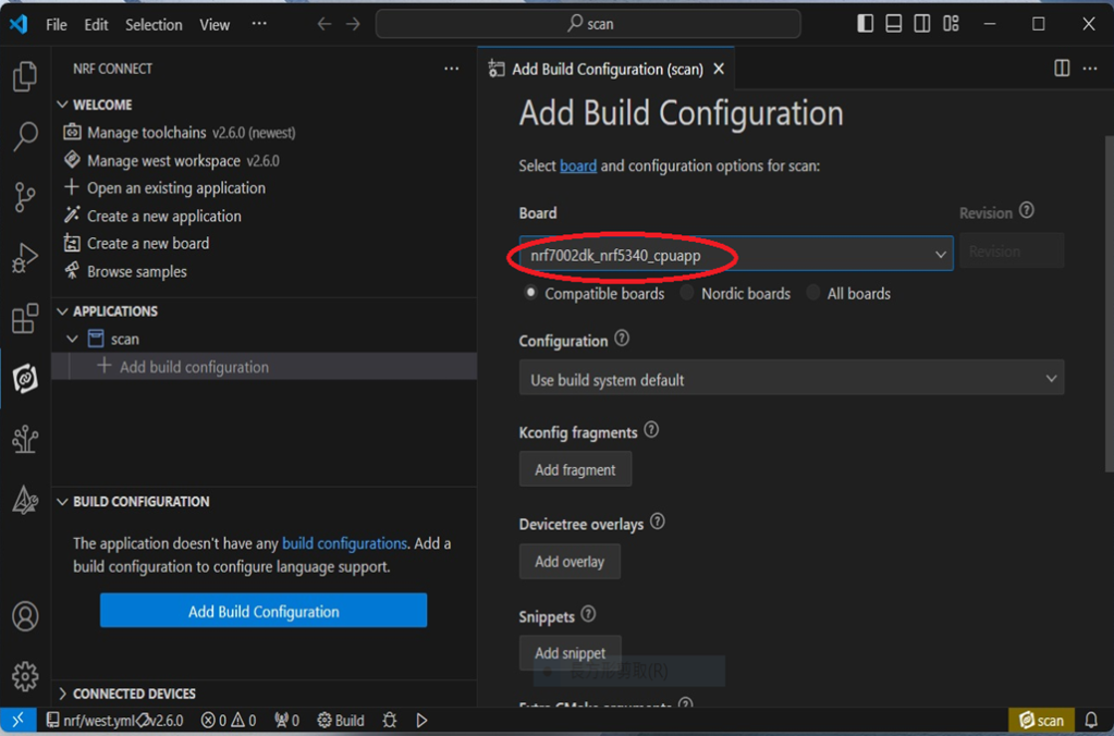
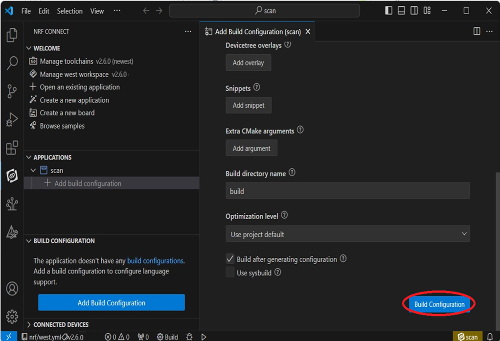
Add build configuration → select the board and compile.
Select board: nrf7002dk_nrf5340_cpuapp.
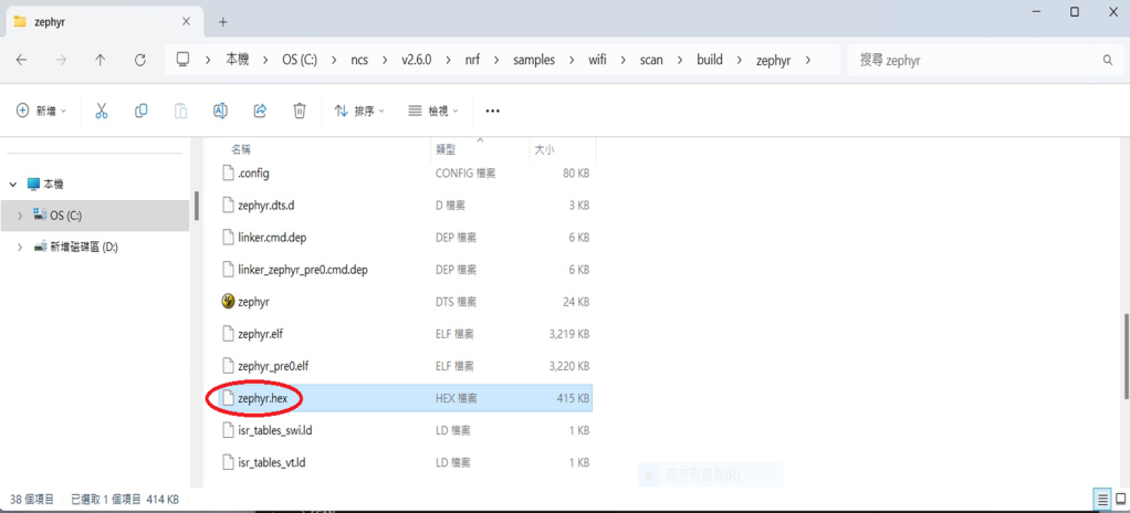
Step7.
After compilation, a hex file will be generated.
Step8.
Under ACTIONS, you can choose to Build, Debug, or Flash.
Build:
Debug:
Flash:
4. Programming
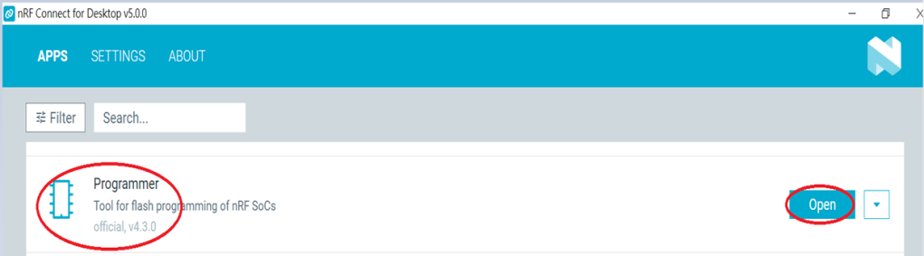
nRF Connect SDK(NCS) supports programming. You can use the “Programmer” tool to flash .hex file. Here’s how:
Step1.
Open “nRF Connect for Desktop” → Select “Programmer” → then click” Open”.
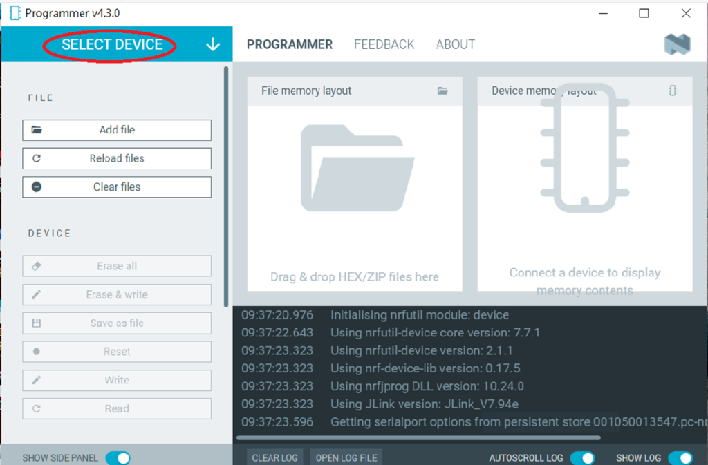
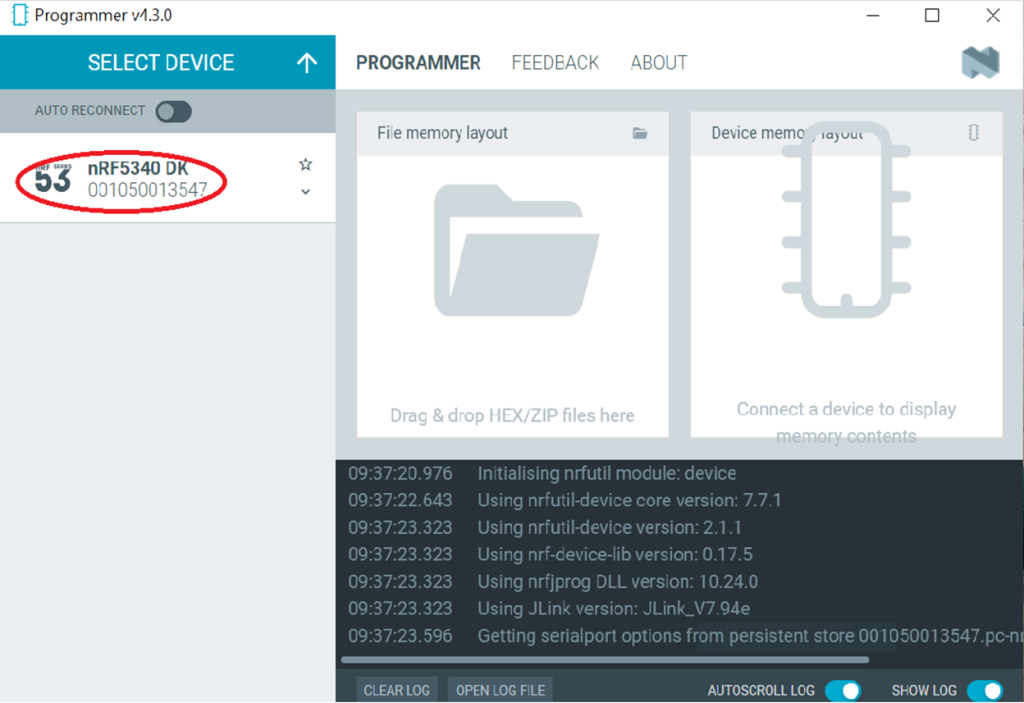
Click “Select Device”;
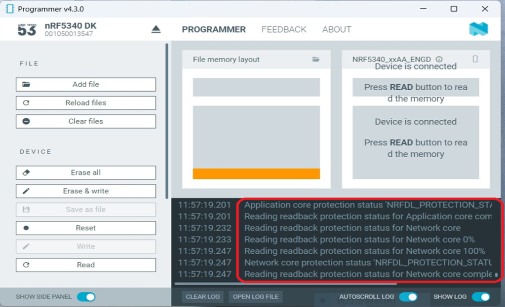
Since AN7002 Wi-Fi IC does not act as an MCU, we can only flash the .hex file into the MDBT53(nRF5340) BLE IC.
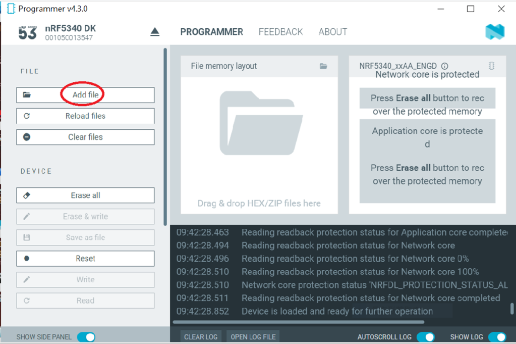
Click “Add file” to add the .hex file.
Step2.
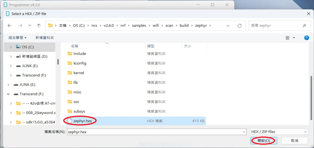
Select the .hex file you want to flash.
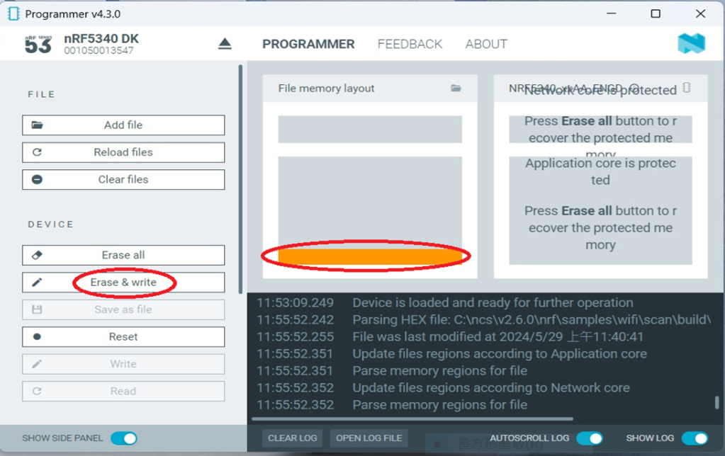
The hex file will be written into the part of the memory layout (where orange part is highlighted).
Slashes will be displayed in the circled part during the flash process.
Step3.
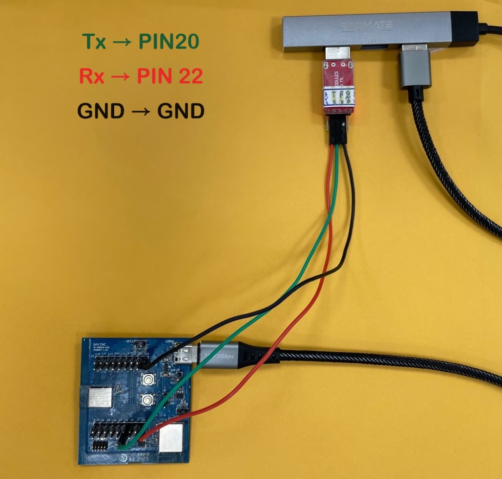
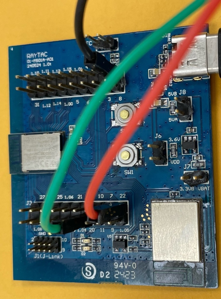
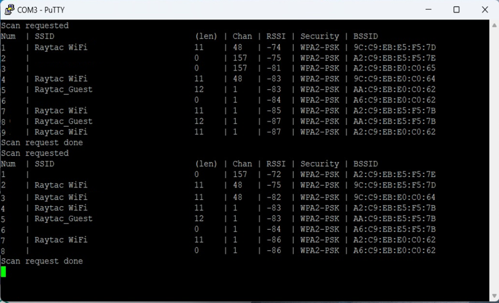
Once the flash process is completed, connect Raytac’s AN7002Q-DB-5340 development board to PuTTY.
Tx to p0.20
Rx to p0.22
GND to GND
This is a closer look into the pins that will be connected.
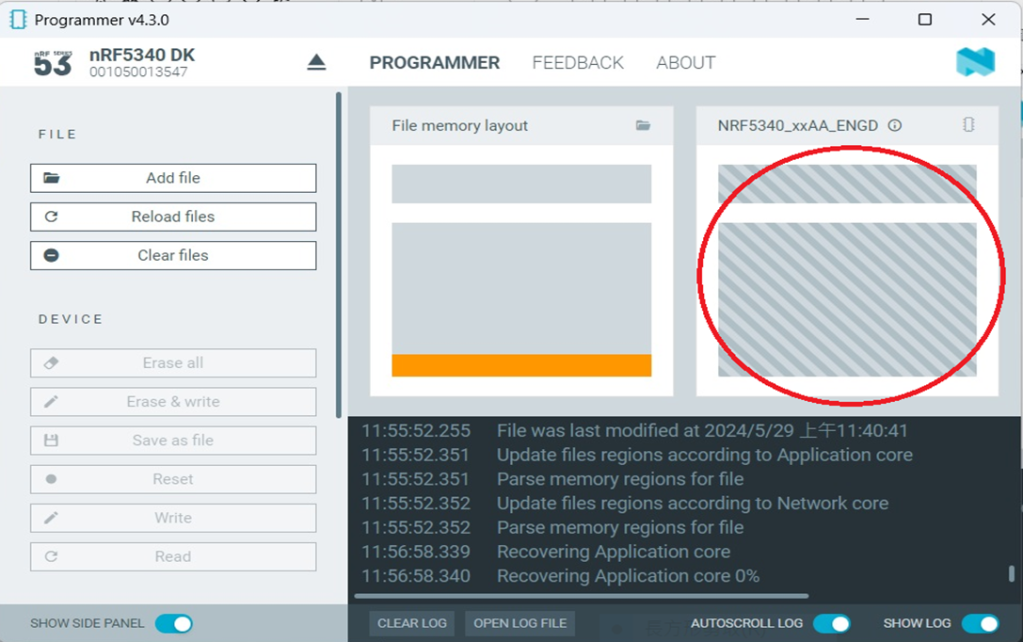
The flash process is completed when the LOG is displayed as circled below.
Check if hardware connection is successful using PuTTY.
*2024-Aug-12 update:* Before running Scan code / Station code / Shell code: You must ensure that the MAC address has already been programmed into the module. Click on this link to learn more about how to load the MAC address.
Edited by Sales Manager: Ms. Vicky Huang Technical guidance provided by R&D Manager: Mr. MW Lee Hardware environment provided by Hardware Engineer: Mr. Kyle Wang
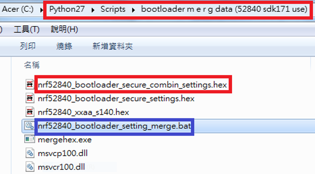
Step 1. Execute the combine batch file in bootloader (nrf52840_bootloader_setting_merge.bat) and generate file ofnrf52840_bootloader_secure_combin_settings.hex :
@echo off title = [ J-Link Tool ] %CD% set nrfDir=C:\Program Files (x86)\Nordic Semiconductor\nrf5x\bin set BS= nrf52840_bootloader_secure_settings.hex set BL= nrf52840_xxaa_s140.hex set BSBLCombind= nrf52840_bootloader_secure_combin_settings.hex set path=%nrfDir%;%path% pause echo ———–merge image file——————- mergehex.exe -m %BS% %BL% -o %BSBLCombind% pause
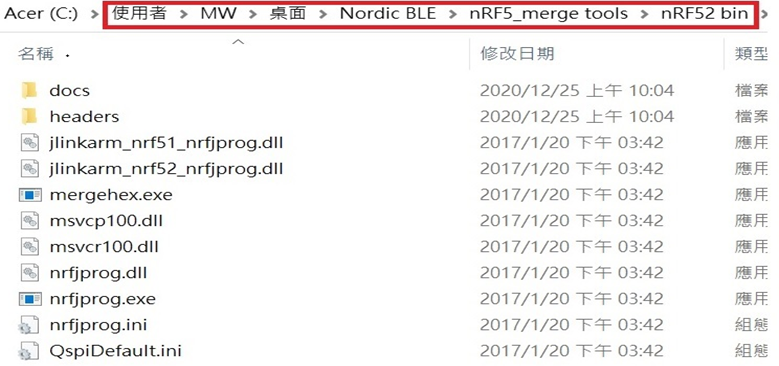
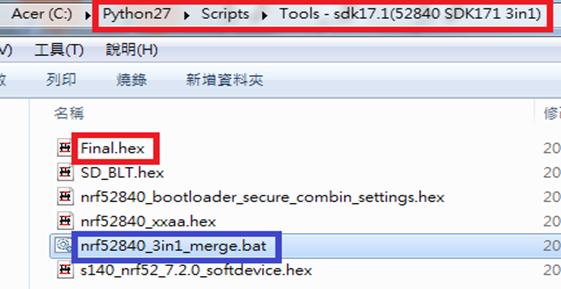
Step 2. Create a Final.hex file by 3-in-1 batch file(nrf52840_3in1_merge.bat) ※Note : This hex file is created for the production line to pre-load firmware into modules prior to shipment.
@echo off title = [ J-Link Tool ] %CD% set nrfDir=C:\Users\user\Desktop\Nordic BLE\nRF5_merge tools\nRF52 bin set SD= s140_nrf52_7.2.0_softdevice.hex set BLT= nrf52840_bootloader_secure_combin_settings.hex set APP= nrf52840_xxaa.hex set SD_BLT=SD_BLT.hex set Finalfile=Final.hex set path=%nrfDir%;%path% pause echo ———–merge image file——————- mergehex.exe -m %SD% %BLT% -o %SD_BLT% pause mergehex.exe -m %SD_BLT% %APP% -o %Finalfile% pause
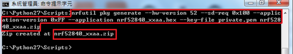
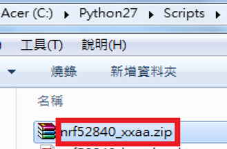
Step 3. Create a DFU(OTA).zip file of nrf52840_xxaa.zip ※Note : This zip file is created for end device DFU(OTA) implementation.
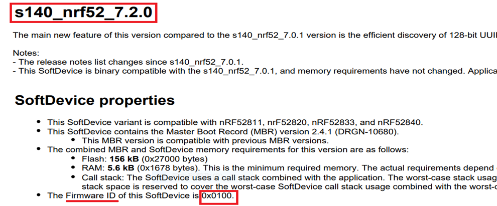
※Note : The “0x100" appeared in the above DOS code(in red font) is the FWID(Firmware ID) for s140_nrf52_7.2.0_softdevice.hex; FWID can be found from the soft device documents on the Nordic website.
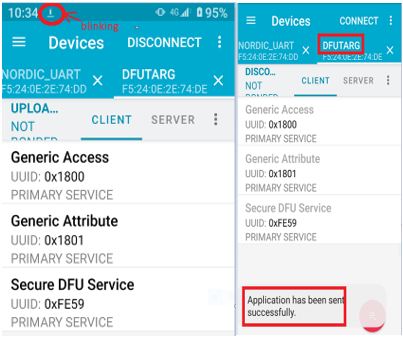
Step 4: Run DFU OTA (On mobile in this example)
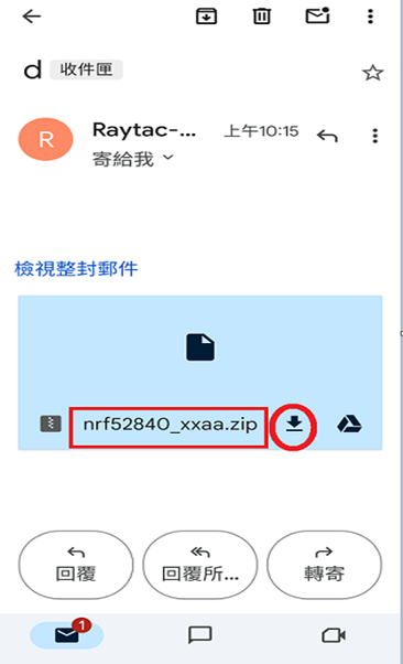
4A. Install the nRF Connect APP on mobile, with DFU OTA file: nrf52840_xxaa.zip.(Download link)
4B. Send nrf52840_xxaa.zip via email to mobile device after combination is done on PC, then download it.
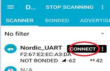
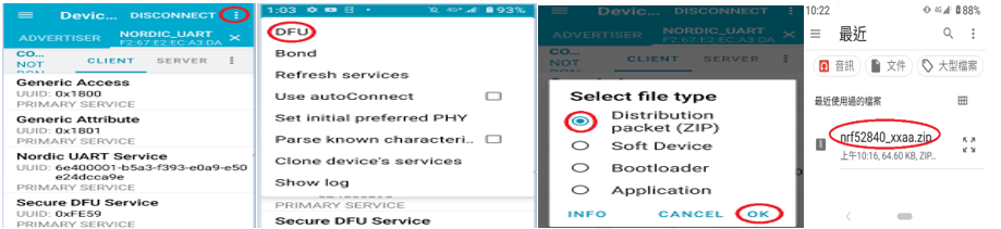
4C. Open nRF Connect APP and run connection;
4D. Execute DFU and select “Distribution packet(ZIP)", thus starting the DFU OTA process.
4E. Start DFU OTA → exit the APP after DFU OTA is completed → restart the mobile device.