Raytac’s AN54LQ & AN54LV modules, powered by Nordic Semiconductor’s nRF54L family SoCs, come in multiple form factors and antenna options, ensuring your seamless integration into compact, RF-sensitive, or performance-driven designs.
Whether you need a: ☑ Chip antenna; ☑ PCB antenna; ☑ u.FL connector; ☑ Antenna Pin,
Or you want Small, Smaller, or Smallest, we always have a solution that fits best! *All products are pre-certified with FCC, IC, CE, UKCA, Telec, KC, SRRC, NCC, RCM, WPC.
New U.S. Headquarter Address: 17800 Castleton Street, Suite 238, City of Industry, CA 91748, USA Phone: 626.328.3827 Our new location strengthens our operational capabilities in the United States, enabling faster logistics, enhanced customer support, and expanded service coverage. We look forward to continuing to serve our partners and customers from our new facility.
Raytac Corporation 勁達國際電子股份有限公司 / Raytac Corporation (USA) / abietec Inc. A Bluetooth, Wi-Fi, and LoRa Module Maker/ODM & OEM Manufacturer based on Nordic nRF54; nRF53: nRF52; nRF51; nRF7002 Semtech Specification: SX1262
Raytac would like to officially announce a Product Change Notice (PCN) for our Bluetooth Low Energy modules based on Nordic Semiconductor’s nRF54L series SoCs, including the nRF54L15, nRF54L10, and nRF54L05. This update specifically concerns the Part Number (PN) changes for improved clarity and product identification across our lineup.
Affected Models Please refer to the table/list below for the full details of the updated part numbers. (Click on the image to zoom in)
Reminder This PCN involves part number naming only. There are no changes to product function, performance, quality, form factor, or safety compliance. All existing certifications and technical documentations remain valid.
We kindly invite our customers, distributors, and partners to update your records accordingly. For any questions or support regarding this update, feel free to reach out via: service@raytac.com
Raytac Corporation 勁達國際電子股份有限公司 / Raytac Corporation (USA) A Bluetooth, Wi-Fi, and LoRa Module Maker/ODM & OEM Manufacturer based on Nordic nRF54; nRF53: nRF52; nRF51; nRF7002 Semtech Specification: SX1262
This guide teaches you how to use MCUboot for DFU (Device Firmware Update), Combined with nRF Connect SDK (NCS) V2.9.1 to upgrade firmware on Raytac’s MDBT50Q series modules.
Table of contents:
Hardware Set Up
Software Kits resource download & install
Compile and load the program a. Open VS Code b. Project setup c. Setup the situation for DFU over UART or DFU over USB d. Start compiling your project e. Load your compiled program into the MDBT50Q-DB-40 demo board
Install nRF Connect for Desktop ➔ install Programmer and Toolchain Manager.
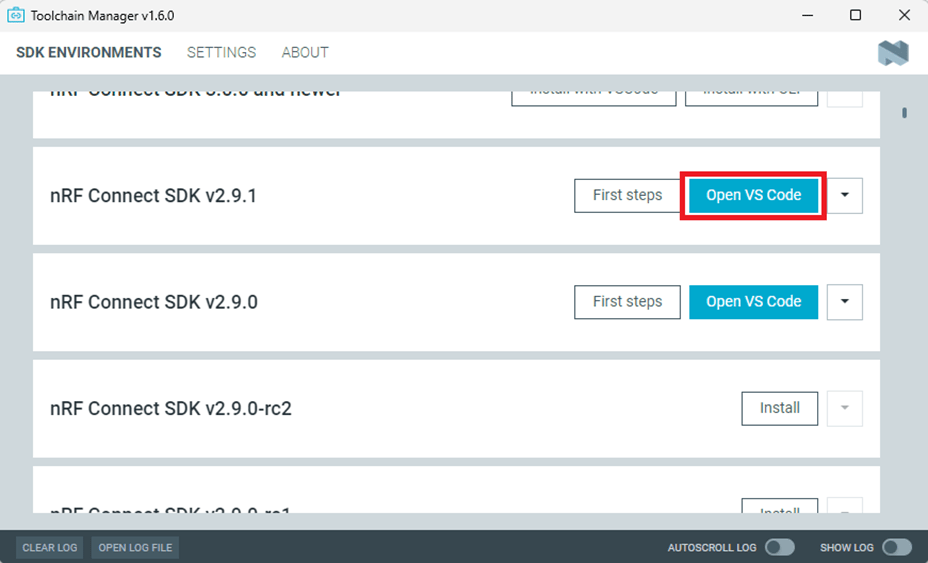
Open Toolchain Manager and install SDK V2.9.1.
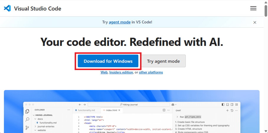
Install Visual Studio Code
3. Compile and load the program a. Open VS Code(Visual Studio Code)
Note: If it’s your first time using the software: after installing all the extensions, you should see the same on your screen.
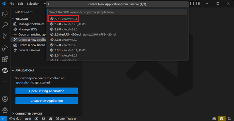
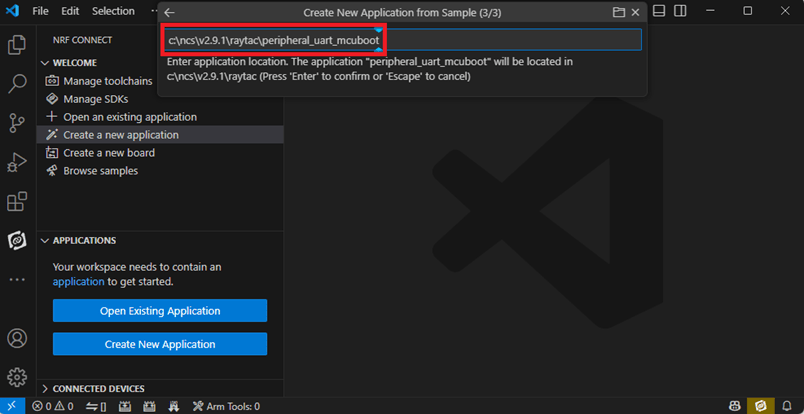
b. Project setup b.1 Create an example code(In this article: peripheral_uart) Please refer to the following steps: Create a new application ➔ Copy a sample ➔ NCS V2.9.1
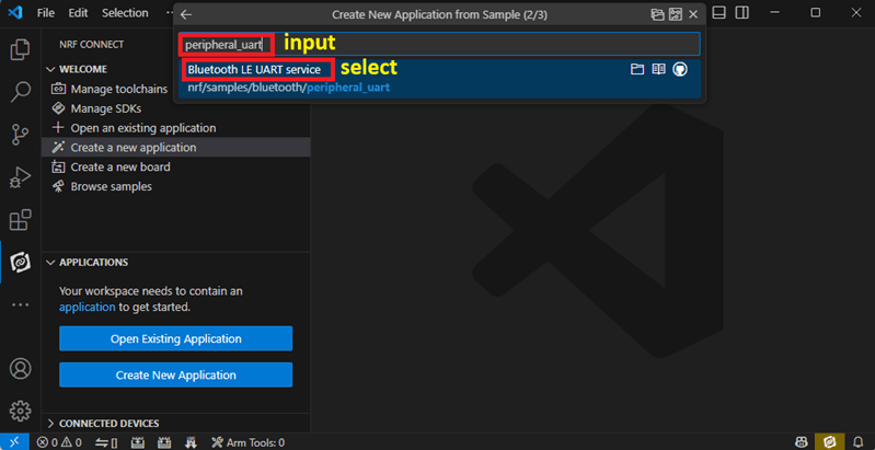
b.2 Name the Project: peripheral_uart Input peripheral_uart and the corresponding example program will appear in the options section below.
Note: We named the project peripheral_uart_mcuboot to distinguish it. This project will create a directory named peripheral_uart_mcuboot.
c.Build an environment for DFU over UART or DFU over USB – Create a new application ➔ Open
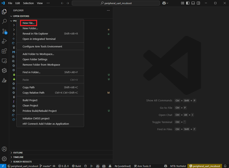
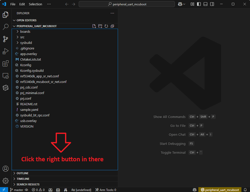
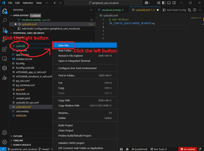
Right click on the project name you just created (peripheral_uart_mcuboot), a pop-up menu will appear. Select the first option “Show in Explorer" from the pop-up menu to display all project files.
Then select New File to create a sysbuild.conf file.
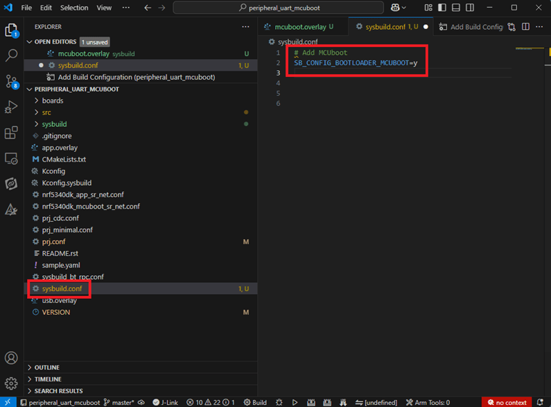
select sysbuild.conf, left-click on it, and a blank box will show.
Input the file name and write: SB_CONFIG_BOOTLOADER_MCUBOOT=y
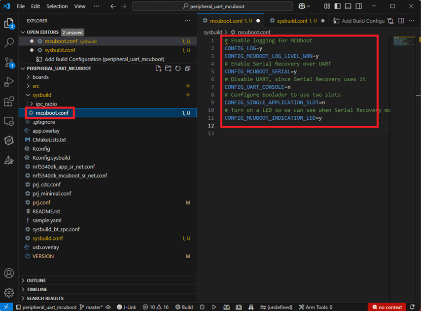
Parameters and instructions Add a new file mcuboot.conf, in the sysbuild folder, and input the following parameters into the file. (Add relevant parameters according to UART or USB) (Note: Please be informed if you want to use DFU over UART in the end, you should use UART when you first create the environment. Similarly, if you want to use DFU over USB, you should create the USB environment at the beginning.)
For DFU over UART # Enable logging for MCUboot CONFIG_LOG=y CONFIG_MCUBOOT_LOG_LEVEL_WRN=y # Enable Serial Recovery over UART CONFIG_MCUBOOT_SERIAL=y # Disable UART, since Serial Recovery uses it CONFIG_UART_CONSOLE=n # Configure the bootloader to use two slots CONFIG_SINGLE_APPLICATION_SLOT=n # Turn on a LED so we can see when Serial Recovery mode is active CONFIG_MCUBOOT_INDICATION_LED=y
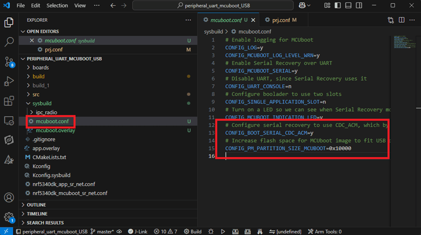
For DFU over USB # Enable logging for MCUboot CONFIG_LOG=y CONFIG_MCUBOOT_LOG_LEVEL_WRN=y # Enable Serial Recovery over UART CONFIG_MCUBOOT_SERIAL=y # Disable UART, since Serial Recovery uses it CONFIG_UART_CONSOLE=n # Configure bootloader to use two slots CONFIG_SINGLE_APPLICATION_SLOT=n # Turn on a LED so we can see when Serial Recovery mode is active CONFIG_MCUBOOT_INDICATION_LED=y # Configure serial recovery to use CDC_ACM, which by default uses the USB CONFIG_BOOT_SERIAL_CDC_ACM=y # Increase flash space for the MCUboot image to fit USB drivers CONFIG_PM_PARTITION_SIZE_MCUBOOT=0x10000
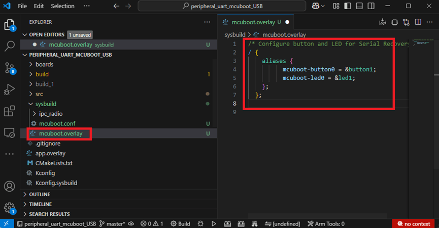
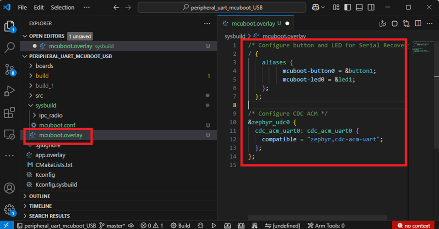
Create a new file: mcuboot.overlay and add the following parameters.
For DFU over UART /* Configure button and LED for Serial Recovery */ / { aliases { mcuboot-button0 = &button0; mcuboot-led0 = &led0; }; };
For DFU over USB /* Configure button and LED for Serial Recovery */ / { aliases { mcuboot-button0 = &button0; mcuboot-led0 = &led0; }; }; /* Configure CDC ACM */ &zephyr_udc0 { cdc_acm_uart0: cdc_acm_uart0 { compatible = “zephyr,cdc-acm-uart"; }; };
Note: if you use DFU over USB, please enable the USB subsystem in prj.conf.
After all the setup is completed, you can start compiling your project.
d. Start compiling your project Add Build Configuration ➔ Select target board ➔ In this example, choose raytac_mdbt50q_db_40/nrf52840.
Start compiling by clicking “Generate and Build" at the bottom-right corner.
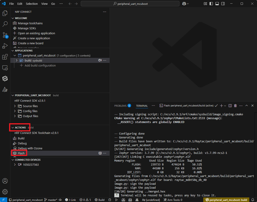
e. Load your compiled program into the MDBT50Q-DB-40 demo board After compiling without error, select the flash function to load your program into the MDBT50Q-DB-40 demo board.
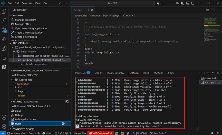
If the below is shown, it means that you have successfully loaded your program into the demo board.
4. DFU to MDBT50Q-DB-40 through UART / USB DFU over UART Hold the SW2 button then plug the power into the USB connector. The system will enter the bootloader mode. You can then DFU the new firmware via the UART.
DFU over USB If you update your firmware through USB, please also hold the SW2 button and connect the USB cable.
Steps: Select the tab Config to set the correct COM port.
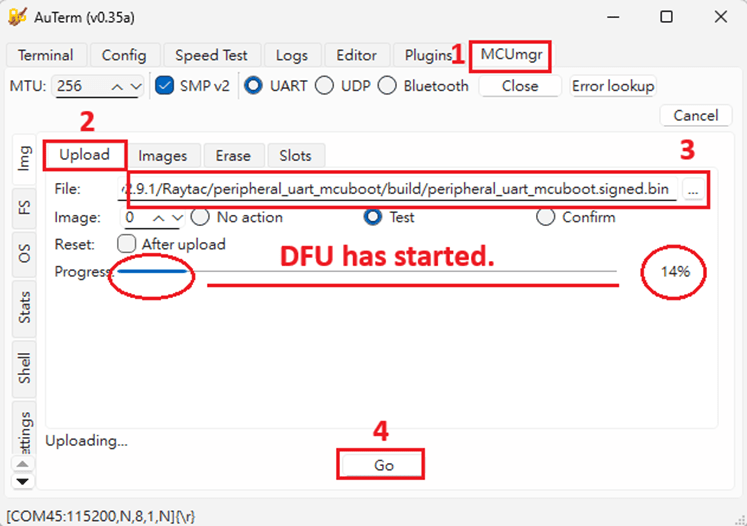
Follow the sequences in the below screenshot.
You can use the file peripheral_uart_mcuboot.signed.bin for testing. It is located in peripheral_uart_mcuboot/build. Then follow the sequences in the below screenshot. DFU will be completed when the progress reaches 100%.
6. DFU using your custom keys When you compile the code, you will see the below warning. Reason: It’s required to have your own private key to ensure your product’s security. Following are the steps to enable security features.
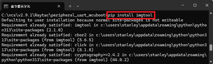
Step 1. Create the key First, install the imgtool program using pip.
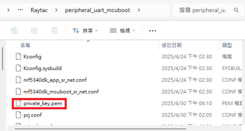
Then use the following command to generate your private key in your project folder. After the private key is generated, you can access it in your directory.
Step 2. Configure the project to use this key in sysbuild.conf
# Add MCUboot SB_CONFIG_BOOTLOADER_MCUBOOT=y #Add private key for MCUboot SB_CONFIG_BOOT_SIGNATURE_KEY_FILE="\${APP_DIR}/private_key.pem" # Configure key type SB_CONFIG_BOOT_SIGNATURE_TYPE_ECDSA_P256=y
Step 3. Build and flash the project again. Your firmware will have security features.
Edited by Account Manager: Mr. Welson Kuo
Raytac Corporation 勁達國際電子股份有限公司 / Raytac Corporation (USA) A Bluetooth, Wi-Fi, and LoRa Module Maker/ODM & OEM Manufacturer based on Nordic nRF54; nRF53: nRF52; nRF51; nRF7002 Semtech Specification: SX1262