[New Taipei City, Taiwan – January 12, 2026]
Raytac Corporation, a global leading supplier of Bluetooth, Wi-Fi, and wireless modules, announces a strategic partnership with Acal BFi(Website link) to strengthen wireless connectivity support for customers across Europe.
Through this collaboration, Raytac’s portfolio of pre-certified Bluetooth® Low Energy, Wi-Fi, and Wi-Fi + Bluetooth modules will be supported by Acal BFi’s local application engineering and design-in expertise.
Raytac specializes in short-range RF connectivity, delivering production-ready wireless modules optimized for low power consumption, RF robustness, and fast system integration.
Additionally, Raytac focuses on simplifying wireless design while ensuring stable performance across demanding industrial, medical, and IoT environments.
Raytac’s module portfolio includes ultra-low-power Bluetooth LE modules, Wi-Fi modules, and versatile Wi-Fi + Bluetooth combo solutions designed for reliable radio coexistence and long-term availability.
All Raytac modules are pre-certified to major global regulatory standards, including CE, FCC, IC, UKCA, TELEC, KC, RCM, SRRC, NCC, and WPC, enabling customers to significantly reduce certification time and compliance risk.
“Great ideas deserve great hardware,” said Lyon Liu, CEO, Raytac. “Our mission is to remove complexity from wireless design. Together with Acal BFi, we can now support customers not only with modules, but with the integration expertise to make sure those modules perform in the real world – in metal housings, in noisy RF environments, in medical devices, in smart sensors, wherever reliability matters.”
“Bluetooth and Wi-Fi connectivity is now a core requirement in almost every market we serve – from smart infrastructure and industrial automation to healthcare and sensing,” said Matthias Beuther, Business Development Manager, Acal BFi. “By partnering with Raytac, we are adding a powerful and proven wireless platform to our portfolio. The combination of Raytac’s module technology and our application engineering expertise gives our customers a faster, lower-risk path to market.”
By working closely with Acal BFi’s IoT & Wireless Technology Centre, customers gain access to local technical support covering antenna selection and tuning, power optimization, enclosure considerations, and coexistence validation. This partnership enables a more predictable, minimal-risk path from prototype to volume production for high-reliability wireless products deployed in real-world environments.
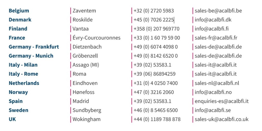
For inquires, please contact the below Acal BFi regional offices:
Edited by Business Development Manager: Tony Yin
Raytac Corporation 勁達國際電子股份有限公司 / Raytac Corporation (USA) / abietec Inc.
A Bluetooth, Wi-Fi, and LoRa Module Maker/ODM & OEM Manufacturer based on
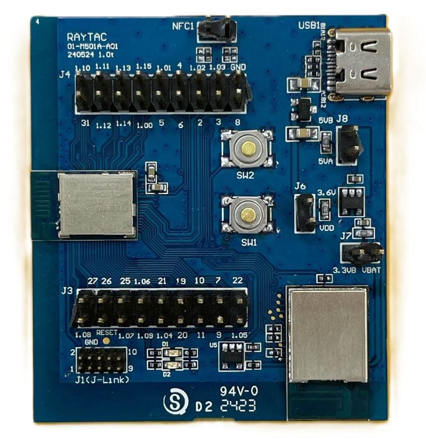
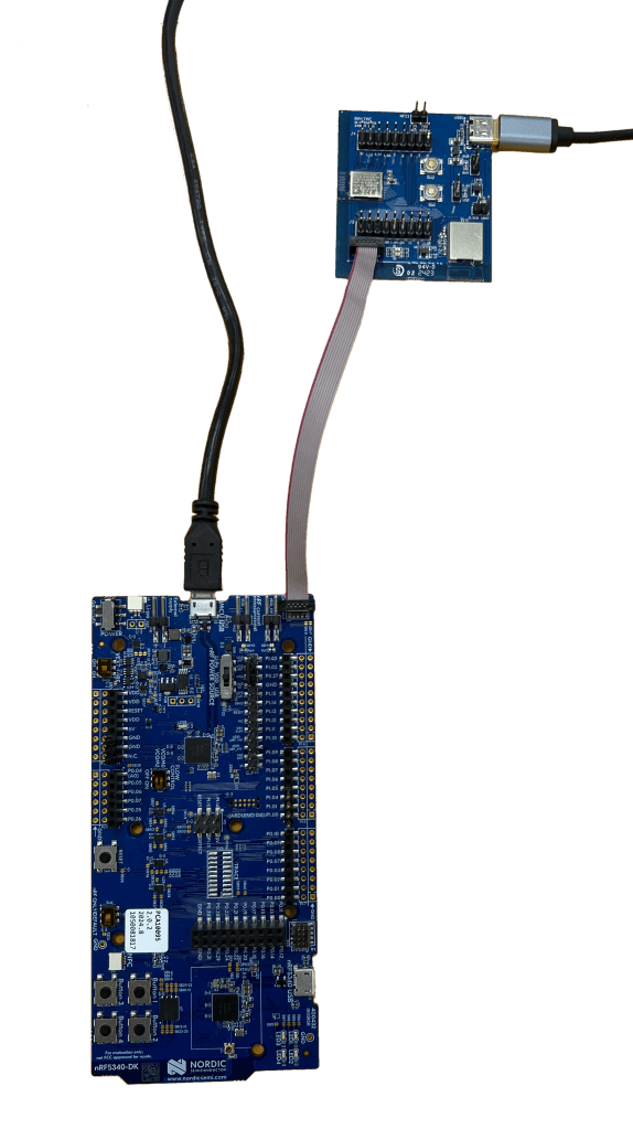
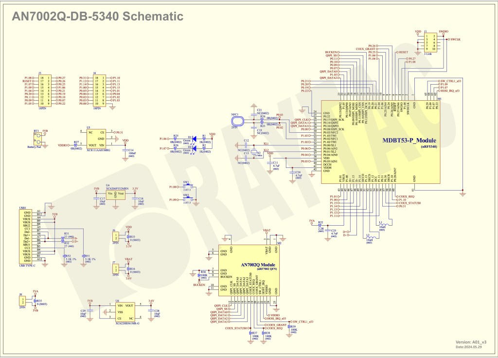
Nordic nRF54; nRF53: nRF52; nRF51; nRF7002
Semtech Specification: SX1262
Bluetooth Specification: BT6 ; BT5.4 ; BT5.3 ; BT5.2.
Wi-Fi Specification: Wi-Fi 6
LoRa Specification: LoRaWAN
All products are FCC/IC/CE/Telec/KC/RCM/SRRC/NCC/WPC/RoHS/Reach Pre-Certified.
http://www.raytac.com
https://www.raytac.com/contact/
email: sales@raytac.com
Tel: +886-2-3234-0208(TW)/+1-626-217-3139(USA)