Raytac has advanced the dev kit version of bundle offer – WIFI+BLE: AN7002Q-DB-
5340-M with an on-board flash memory(MX25R64) to create easy evaluation
for Wi-Fi project developments.
[January 2026 Update]
In this article, we will talk about:
Project WITH External Flash MX25R64(8MB) applied
– Connecting through SPI between nRF5340 module: MDBT53-1M(BLE) & nRF7002 module: AN7002Q(WIFI)
– Connecting through QSPI (XIP) between MDBT53-1M and external memory MX25R64
Table of Content———————————————————————————————————
- Hardware Set Up
A. Project WITHOUT External Flash MX25R64 needed
B. Project WITH External Flash MX25R64 needed - Software Resources & Preparations
- Firmware Build & Compile
A. Project WITHOUT External Flash MX25R64 needed
B. Project WITH External Flash MX25R64 needed - Validate DFU Process & WIFI SCAN
—————————————————————————————————————————-
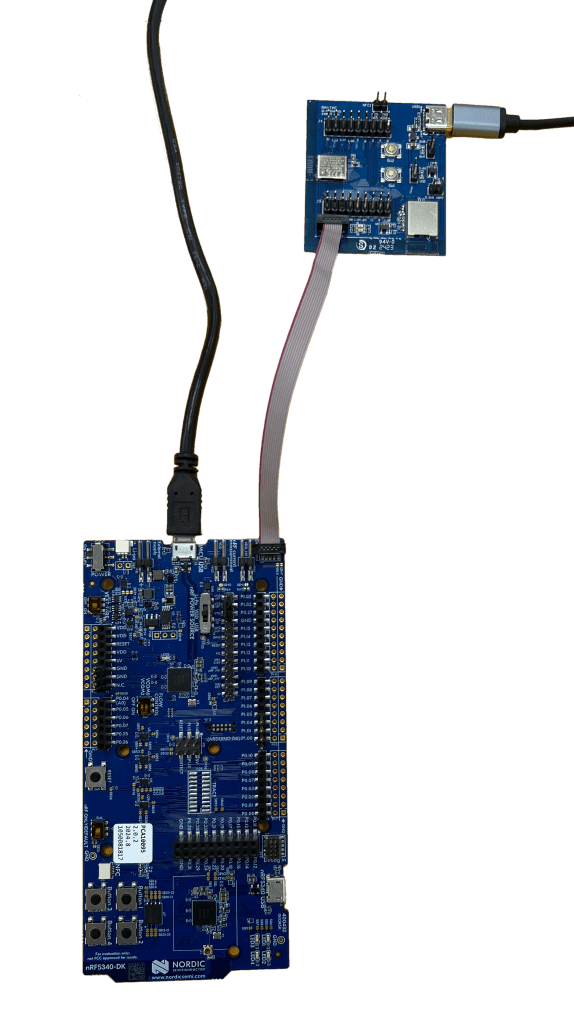
1. Hardware Set Up
Hardware Kit on hand:
- 1 x Nordic nRF5340-DK: PCA10095(2.0.2)
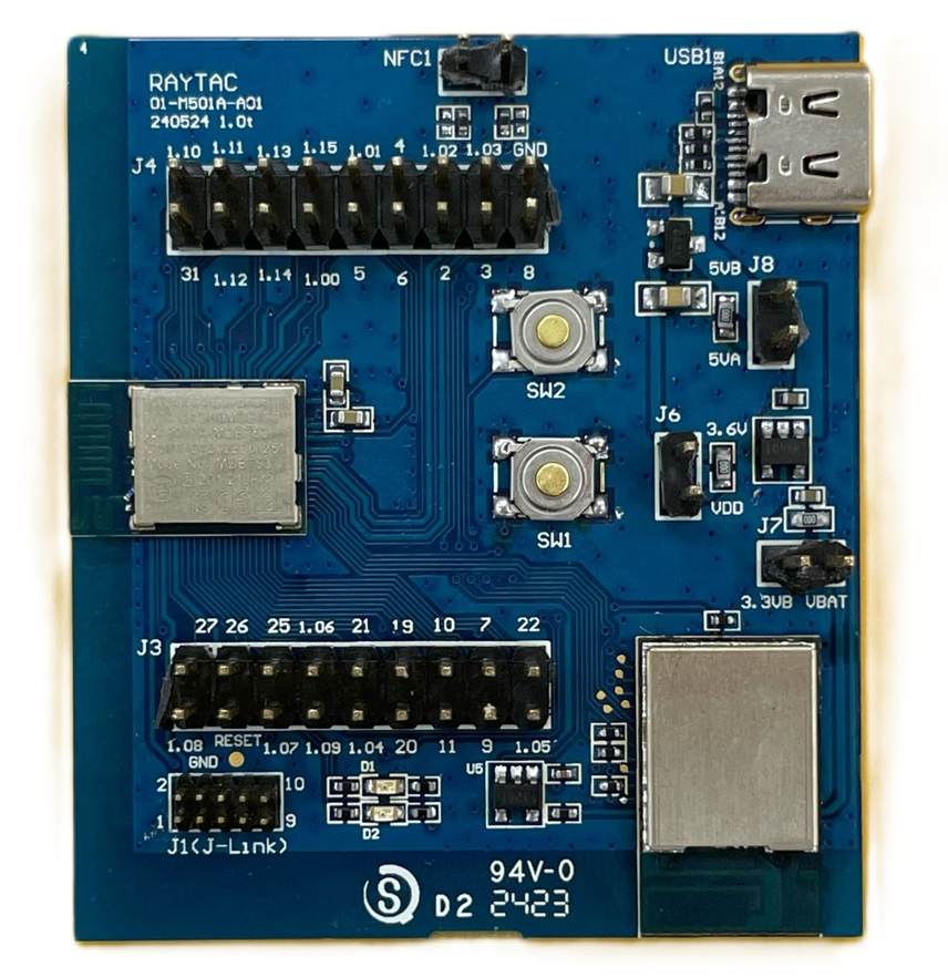
- 1 x AN7002Q-DB-5340-M
- 1 x IDC Ribbon Wire(J-Link Cable)
- 1 x USB Wire –Type C USB
- 1 x USB Wire-Micro USB
Note: Pease make sure to have both “Nordic nRF5340-DK” and “AN7002Q-DB-5340-M” connected and running during the WIFI+BLE (nRF7002+nRF5340) project development.
Hardware Network:
IDC Ribbon Wire(J-Link Cable): Connect nRF5340-DK to AN7002Q-DB-5340-M
USB Wire –Type C USB: Power supply to AN7002Q-DB-5340-M through USB TYPE-C
USB Wire-Micro USB: Power supply to nRF5340-DK through Micro USB

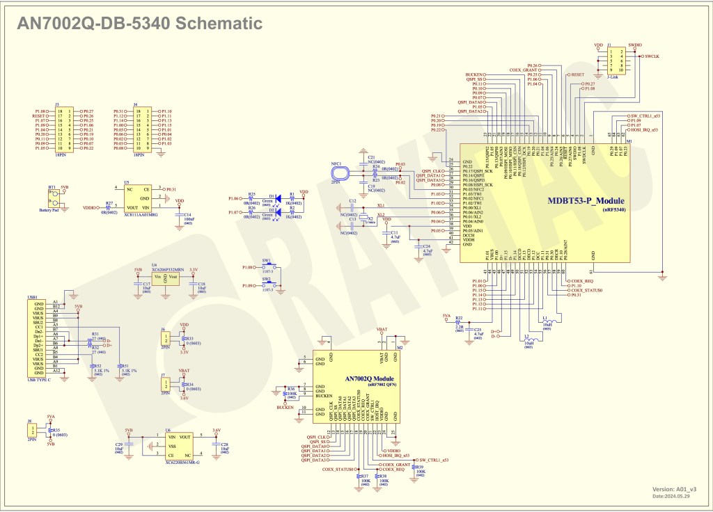
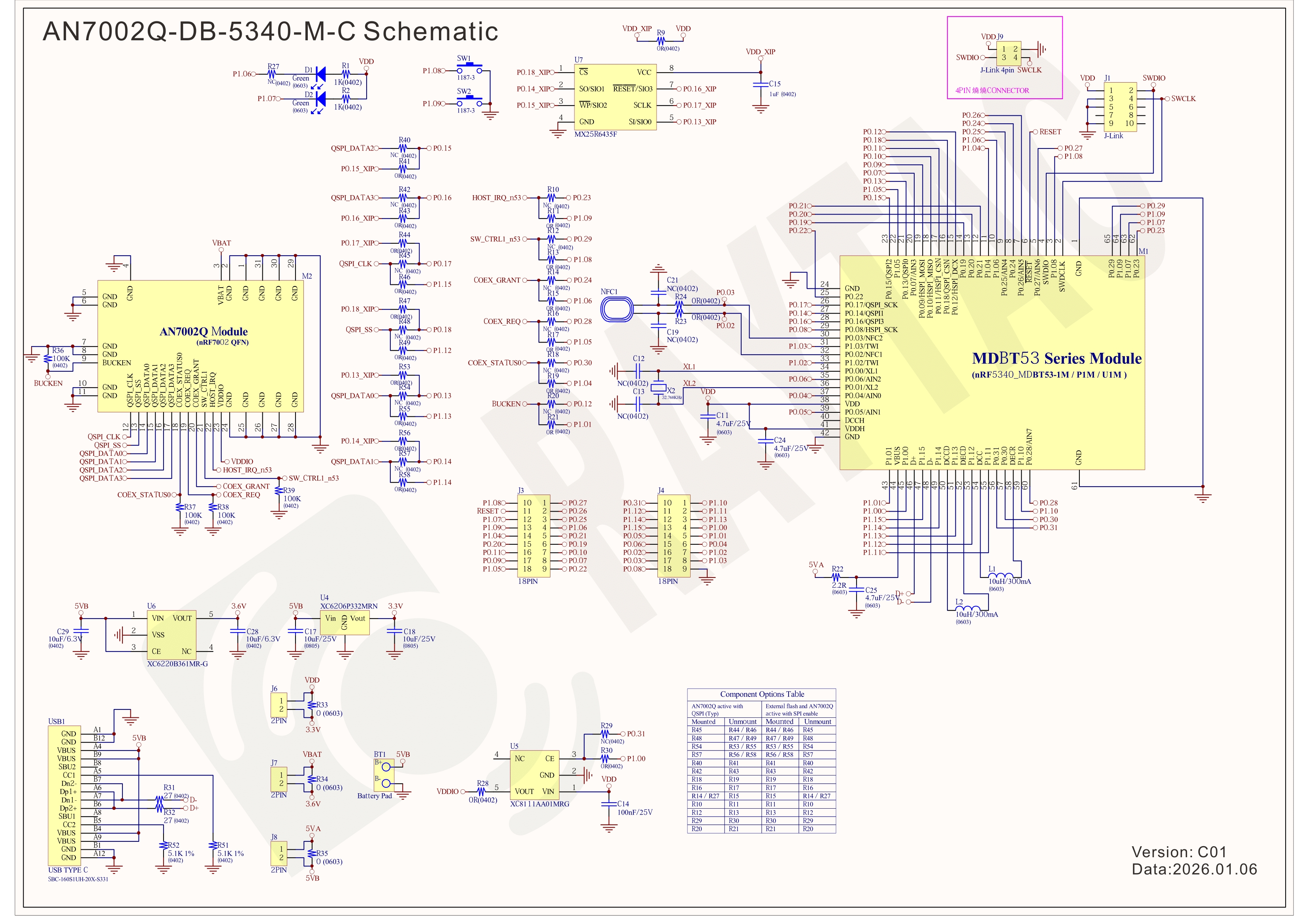
Schematic diagram of AN7002Q-DB-5340-M can be referenced for design as follows.
*nRF7002 module <- SPI -> nRF5340 module
*MX256R NOR Flahs <-QSPI-> nRF7002 module
(Click on the image to zoom in.)
!! Important Note:!!
The circuit of SW1(p1.08)/SW2(p1.09)/LED1(p1.06) on AN7002Q-DB-5340-M is NOT COMPATIBLE to Nordic WI-FI Control Pin of swctrl1(p1.08)/host_irq(p1.09)/grant(p1.06).
In this case, if you’re working with external flash MX25R64 for the WIFI project, Please avoid pin SW1/SW2/LED1 usage while LED2(p1.07) remains available as normal usage.
For the PCB design of end product/end device(mounted with AN7002Q & MDBT53 modules), the switch & LED should be configured to be: SW1(p0.23)/SW2(p0.24)/LED1(p0.28).
2. Software Resources & Preparations
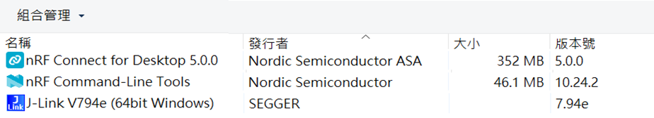
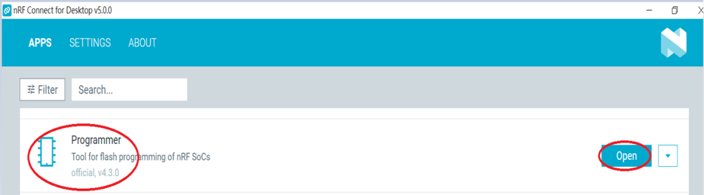
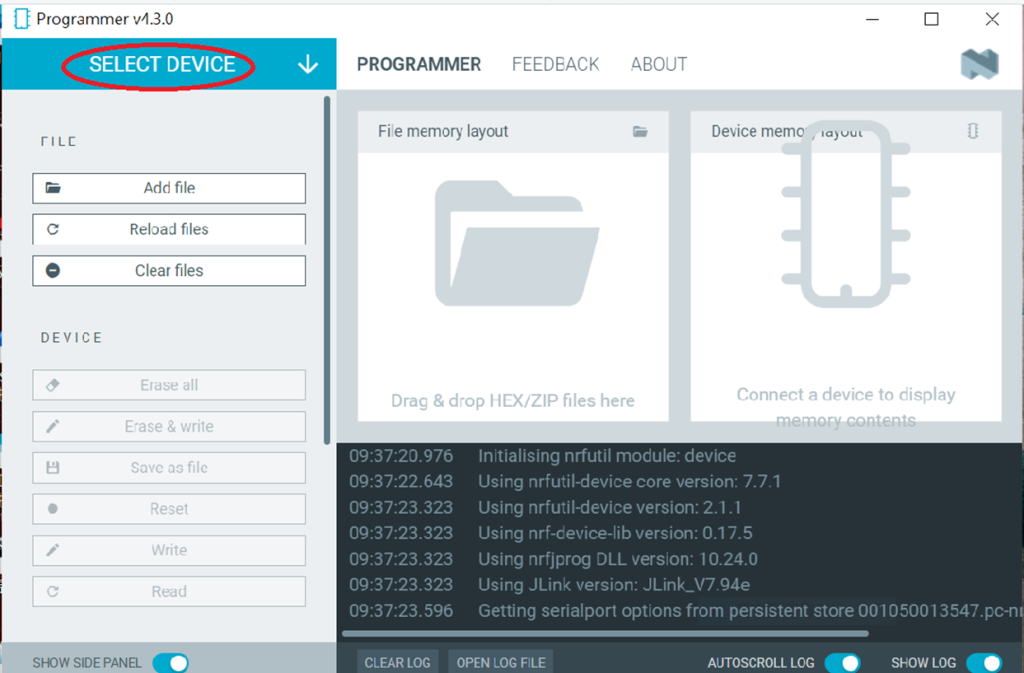
Download nRF Connect For Desktop (Please Click Me)
Download nRF Command Line Tools (Please Click Me)
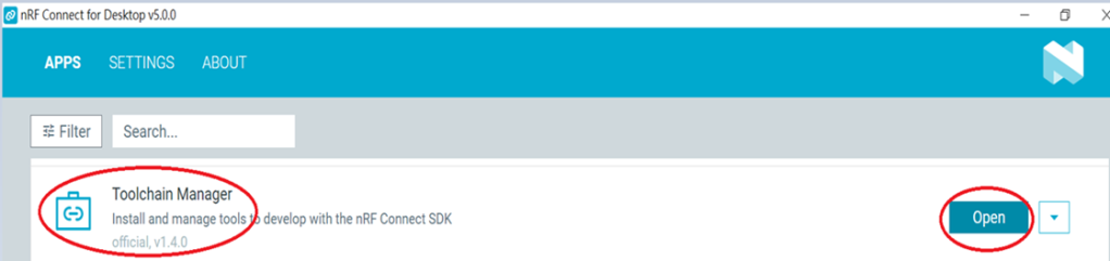
Step 1: Prepared with the latest version of nRF Connect for Desktop, using Windows 64-bit – 5.2.0
Step 2: Prepared with the latest version of Command Line Tools, using Windows X86 64 – 10.24.2
**Note: SEGGER J-LINK Upgrade message might pop up while you’re doing above downloads.

If you’re initiating Segger Embedded Studio (SES) application, please check the guideline here(Click me)
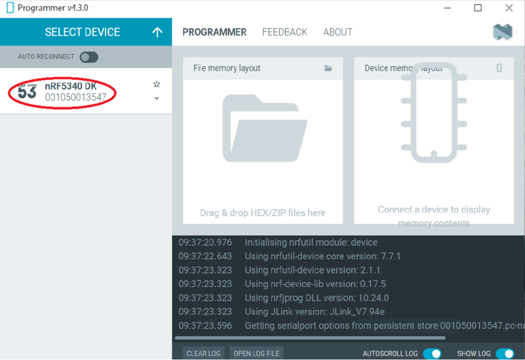
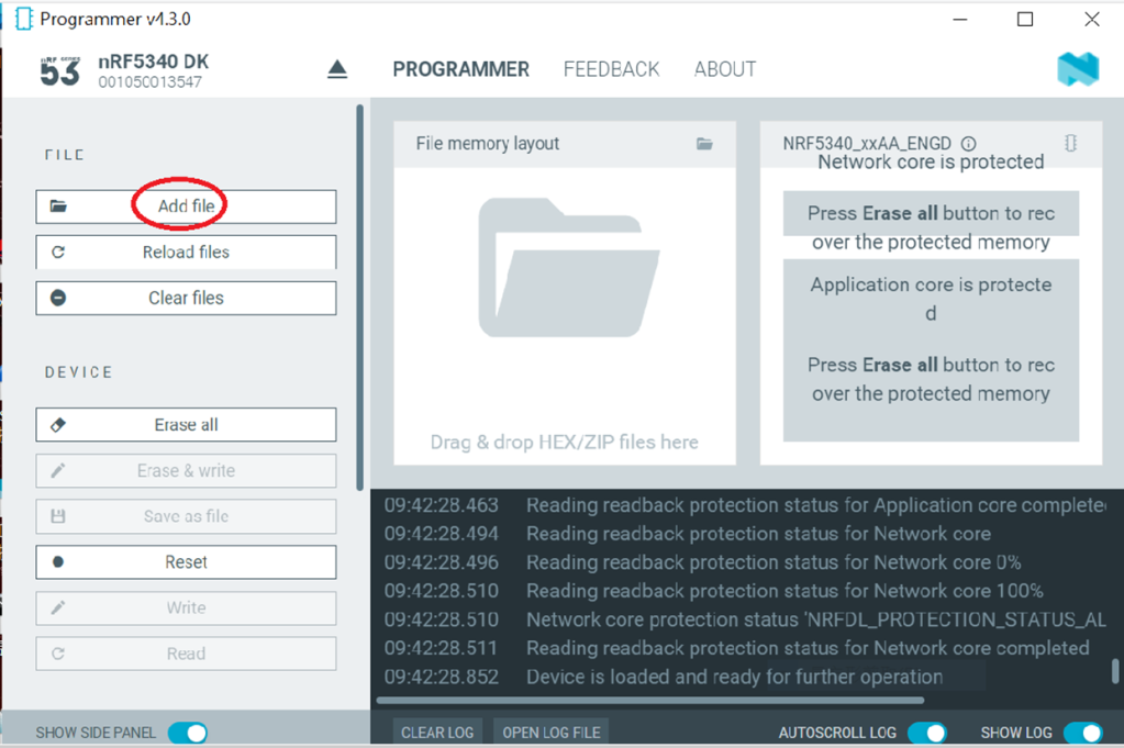
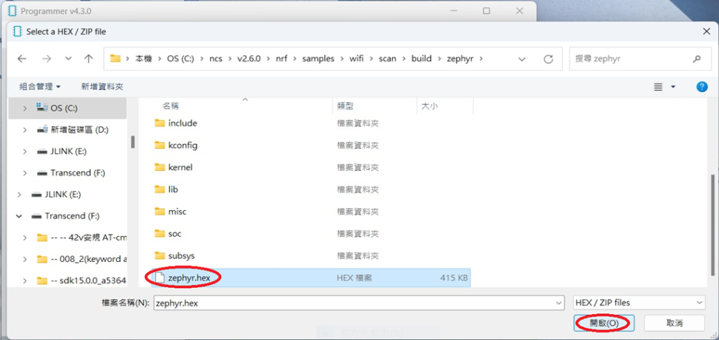
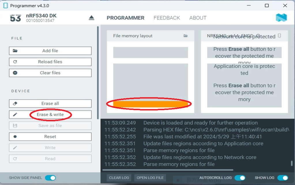
Step 3: Locate all the necessary kits for programming in PC

3. Firmware Build & Compile
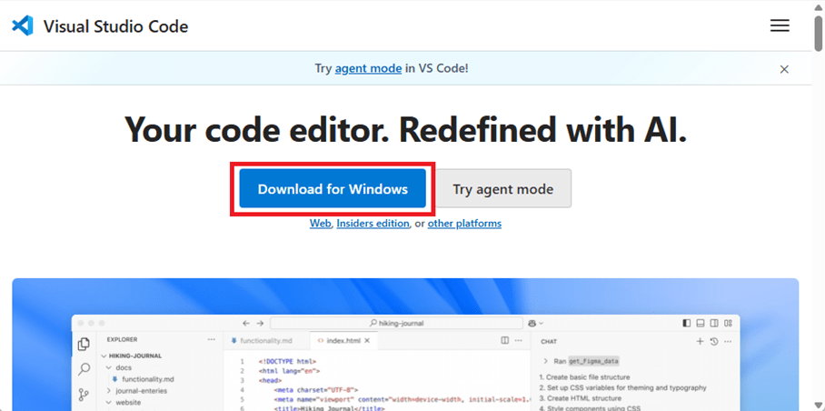
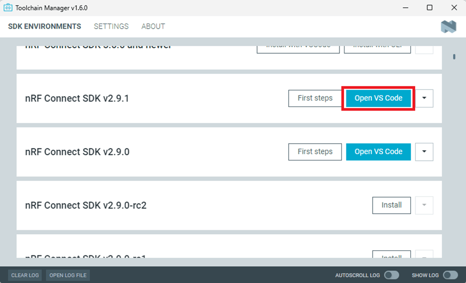
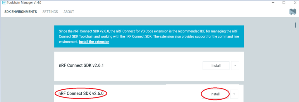
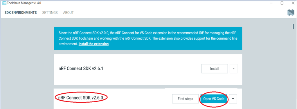
After you download and set up nRFConnect SDK (NCS), you will be able to apply free VS (Visual Studio) Code IDE as firmware programming tool.
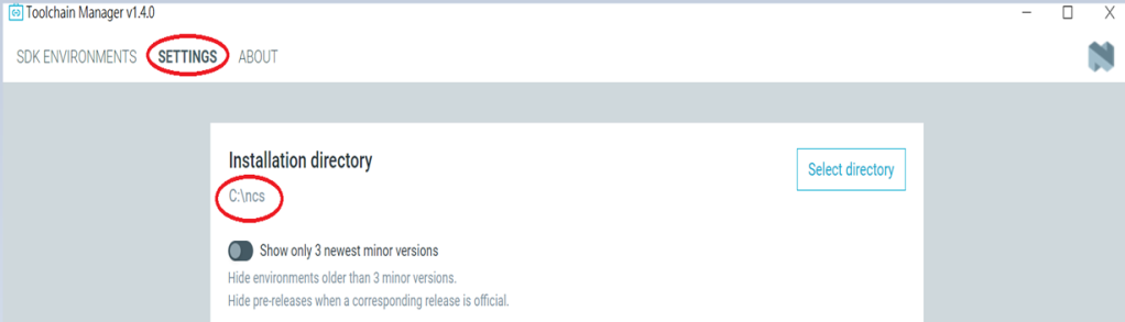
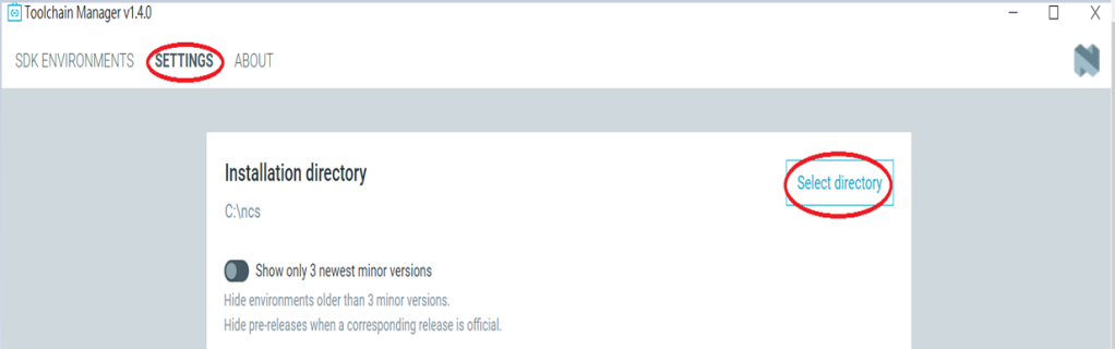
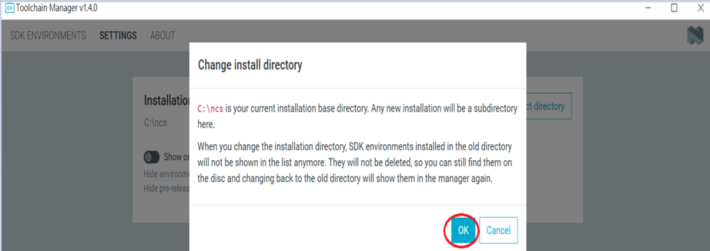
The below example uses NCS v3.1.1 and runs the program under: C:\ncs
Step 1: Start with a Wi-Fi Scan project and run the program under: C:\ncs\v3.1.1\raytac
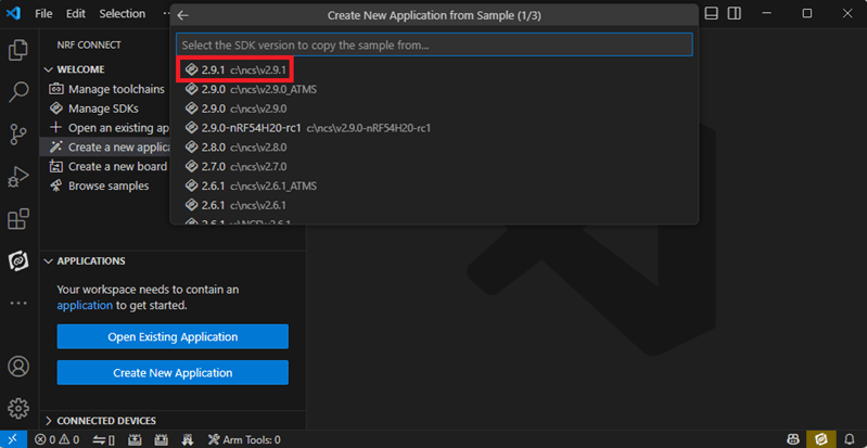
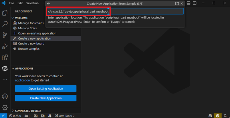
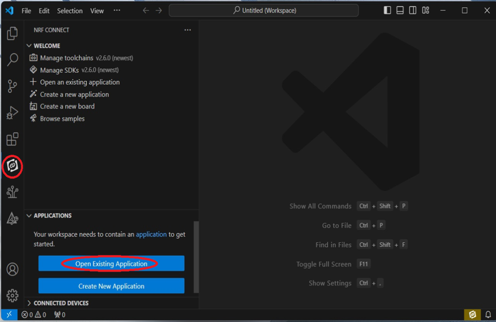
<<Create a new application and Copy a sample>>

Step 2: Select SDK v3.1.1 to copy the sample

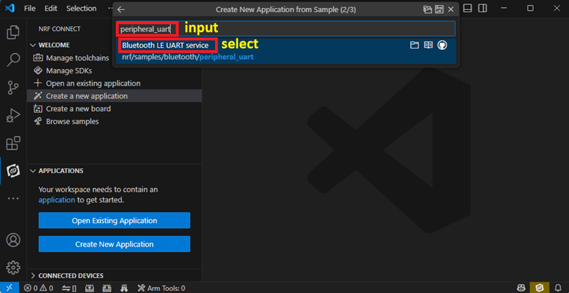
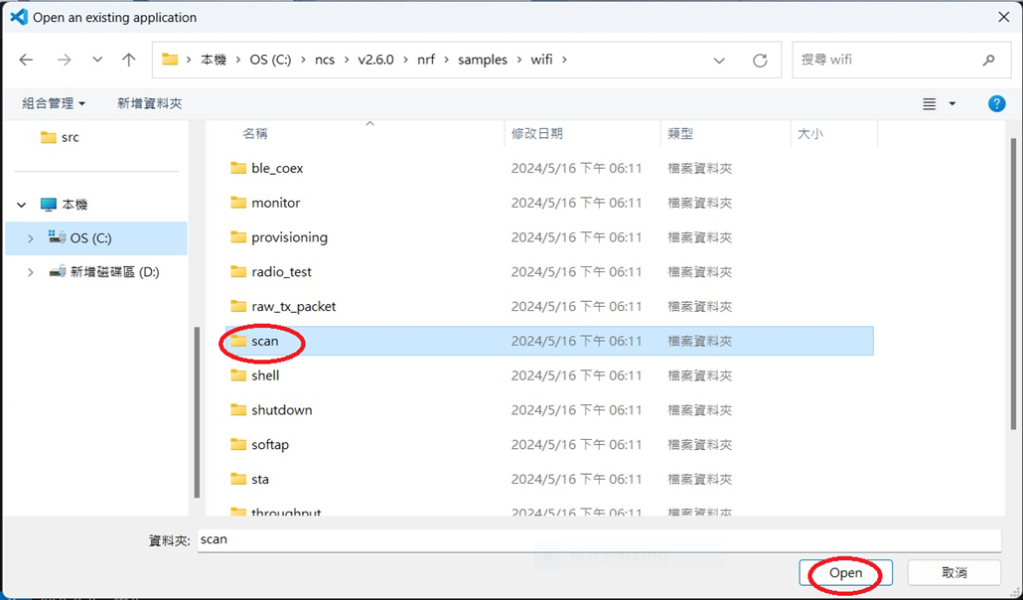
Step 3: Select example by entering keyword: wifi scan(Wi-Fi Scan)

Step 4: Enter application location: C:\ncs\v3.1.1\raytac and name the project as: wifi_scan_uart_dfu


Step 5: Open an existing application and find the registered project: wifi_scan_uart_dfu


Step 6: How to activate the Devicetree setting of Wi-Fi nRF7002 and Create file: nrf5340dk_nrf5340_cpuapp.overlay
Code example is as follows:
/ {
chosen {
aliases {
/delete-node/ leds;
/delete-node/ buttons;
};
};
leds {
compatible = “gpio-leds";
led1: led_1 {
gpios = <&gpio1 7 GPIO_ACTIVE_HIGH>;
label = “Green LED 1″;
};
};
/* These aliases are provided for compatibility with samples */
aliases {
led1 = &led1;
};
};
&mx25r64 {
status = “okay";
};
/ {
chosen {
nordic,pm-ext-flash = &mx25r64;
zephyr,wifi = &wlan0;
};
};
&gpio_fwd {
/delete-node/ uart;
};
&gpio_fwd
{
status = “disabled";
};
&qspi {
status = “okay";
pinctrl-0 = <&qspi_default>;
pinctrl-1 = <&qspi_sleep>;
pinctrl-names = “default", “sleep";
mx25r64: mx25r6435f@0 {
compatible = “nordic,qspi-nor";
reg = <0>;
/* MX25R64 supports only pp and pp4io */
writeoc = “pp4io";
/* MX25R64 supports all readoc options */
readoc = “read4io";
sck-frequency = <8000000>;
jedec-id = [c2 28 17];
sfdp-bfp = [
e5 20 f1 ff ff ff ff 03 44 eb 08 6b 08 3b 04 bb
ee ff ff ff ff ff 00 ff ff ff 00 ff 0c 20 0f 52
10 d8 00 ff 23 72 f5 00 82 ed 04 cc 44 83 68 44
30 b0 30 b0 f7 c4 d5 5c 00 be 29 ff f0 d0 ff ff
];
size = <67108864>;
has-dpd;
t-enter-dpd = <10000>;
t-exit-dpd = <35000>;
};
};
&spi1 {
status = “okay";
compatible = “nordic,nrf-spim";
pinctrl-0 = <&spi1_default>;
pinctrl-1 = <&spi1_sleep>;
pinctrl-names = “default", “sleep";
cs-gpios = <&gpio1 12 GPIO_ACTIVE_LOW >;
nrf70: nrf7002@0 {
status = “okay";
compatible = “nordic,nrf7002-spi";
reg = <0>;
spi-max-frequency = <24000000>;
/* Wi-Fi Pins used */
iovdd-ctrl-gpios = <&gpio1 0 GPIO_ACTIVE_HIGH>;
bucken-gpios = <&gpio1 1 GPIO_ACTIVE_HIGH>;
host-irq-gpios = <&gpio1 9 GPIO_ACTIVE_HIGH>;
wlan0: wlan {
compatible = “nordic,wlan";
};
wifi-max-tx-pwr-2g-dsss = <21>;
wifi-max-tx-pwr-2g-mcs0 = <16>;
wifi-max-tx-pwr-2g-mcs7 = <16>;
wifi-max-tx-pwr-5g-low-mcs0 = <9>;
wifi-max-tx-pwr-5g-low-mcs7 = <9>;
wifi-max-tx-pwr-5g-mid-mcs0 = <11>;
wifi-max-tx-pwr-5g-mid-mcs7 = <11>;
wifi-max-tx-pwr-5g-high-mcs0 = <13>;
wifi-max-tx-pwr-5g-high-mcs7 = <13>;
};
nrf_radio_coex: nrf7002-coex {
status = “okay";
compatible = “nordic,nrf700x-coex";
req-gpios = <&gpio1 5 GPIO_ACTIVE_HIGH>;
status0-gpios = <&gpio1 4 GPIO_ACTIVE_HIGH>;
grant-gpios = <&gpio1 6 (GPIO_PULL_DOWN | GPIO_ACTIVE_LOW)>;
swctrl1-gpios = <&gpio1 8 GPIO_ACTIVE_HIGH>;
};
};
&pinctrl {
spi1_default: spi1_default {
group1 {
psels = <NRF_PSEL(SPIM_SCK, 1, 15)>,
<NRF_PSEL(SPIM_MOSI, 1, 13)>,
<NRF_PSEL(SPIM_MISO, 1, 14)>;
};
};
spi1_sleep: spi1_sleep {
group1 {
psels = <NRF_PSEL(SPIM_SCK, 1, 15)>,
<NRF_PSEL(SPIM_MOSI, 1, 13)>,
<NRF_PSEL(SPIM_MISO, 1, 14)>;
low-power-enable;
};
};
};
/ {
chosen {
zephyr,console = &uart2;
zephyr,shell-uart = &uart2;
};
};
&uart2 {
status = “okay";
current-speed = <115200>;
pinctrl-0 = <&uart2_default>;
pinctrl-1 = <&uart2_sleep>;
pinctrl-names = “default", “sleep";
};
&pinctrl {
uart2_default: uart2_default {
group1 {
psels = <NRF_PSEL(UART_TX, 1, 2)>,
<NRF_PSEL(UART_RX, 1, 3)>;
bias-pull-up;
};
};
uart2_sleep: uart2_sleep {
group1 {
psels = <NRF_PSEL(UART_TX, 1, 2)>,
<NRF_PSEL(UART_RX, 1, 3)>;
low-power-enable;
};
};
};
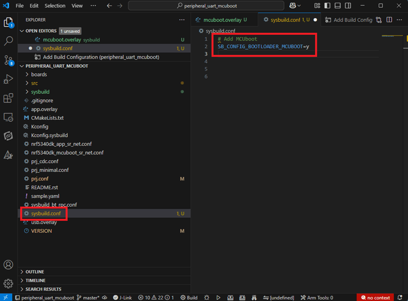
Step 7: It is required to do MCUBoot before working with DFU using External Flash
Please do the code configuration in sysbuild.conf as following reference code.
SB_CONFIG_BOOTLOADER_MCUBOOT=y
# DFU with UART
SB_CONFIG_MCUBOOT_MODE_SINGLE_APP=n
# DFU with external flash
SB_CONFIG_PM_EXTERNAL_FLASH_MCUBOOT_SECONDARY=y
Step 8: It is required to doMCUMGR before working with DFU over UART
Please do the code configuration in prj.conf as following reference code.
# Enable QSPI driver for Application
CONFIG_NORDIC_QSPI_NOR=y
# Enable mcumgr DFU in application
CONFIG_MCUMGR=y
CONFIG_NET_BUF=y
CONFIG_ZCBOR=y
CONFIG_CRC=y
# Enable mcumgr management for both OS and Images
CONFIG_MCUMGR_GRP_OS=y
CONFIG_MCUMGR_GRP_IMG=y
CONFIG_FLASH=y
CONFIG_IMG_MANAGER=y
CONFIG_STREAM_FLASH=y
CONFIG_FLASH_MAP=y
# Configure MCUMGR transport to UART
CONFIG_MCUMGR_TRANSPORT_UART=y
CONFIG_BASE64=y
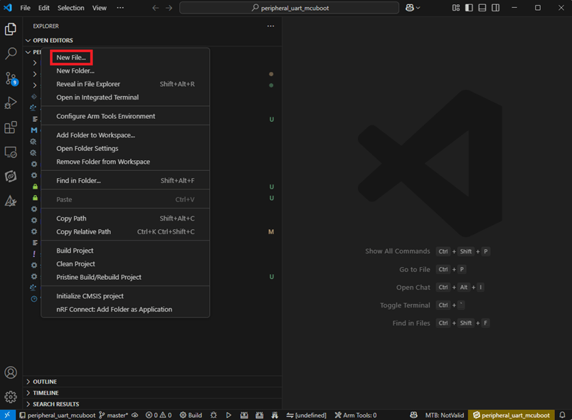
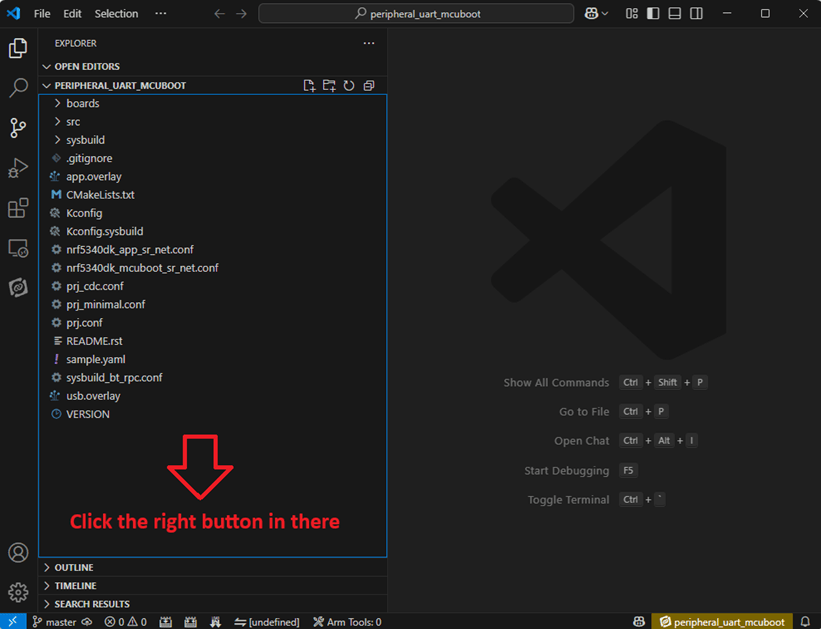
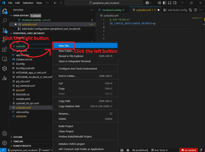
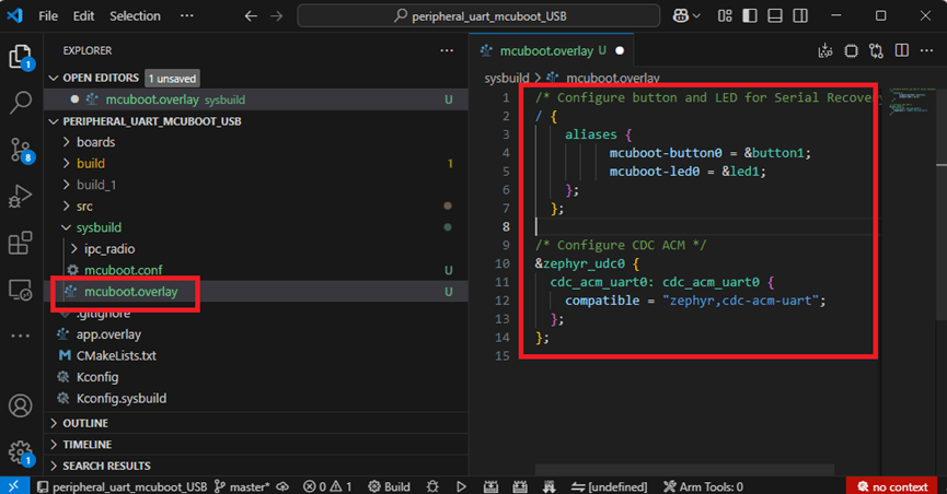
Step 9: Add with MCUBoot setting , and create a root for sysbuild ; Build with file mucboot.overlay & file mcuboot.conf
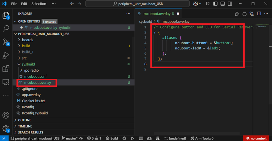
9A. To the File: mucboot.overlay
&mx25r64 {
status = “okay";
};
/ {
chosen {
nordic,pm-ext-flash = &mx25r64;
};
};
&gpio_fwd {
/delete-node/ uart;
};
&gpio_fwd
{
status = “disabled";
};
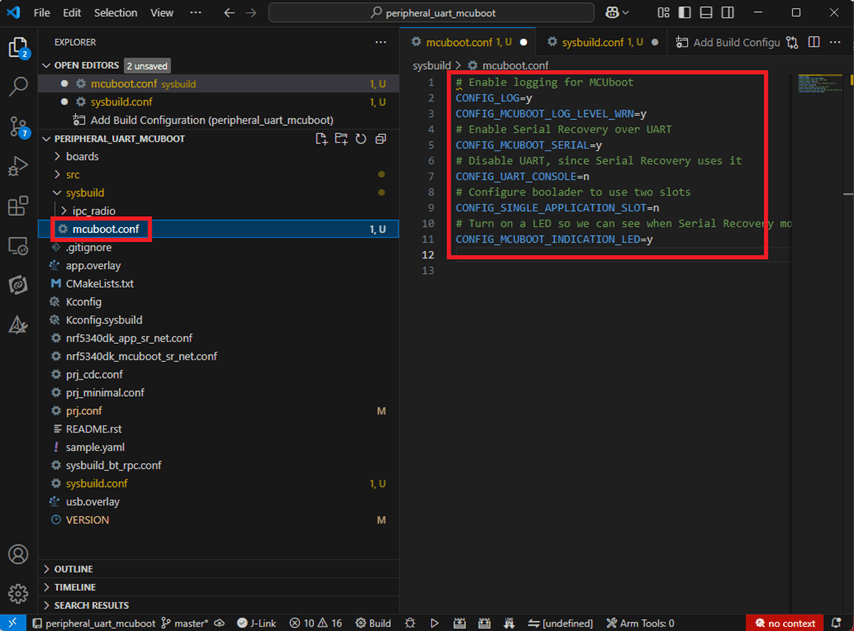
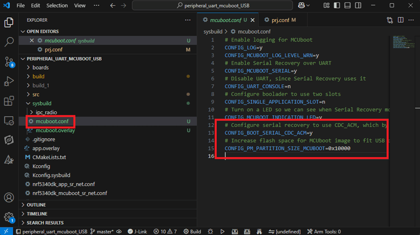
9B. To the File: mcuboot.conf
CONFIG_NORDIC_QSPI_NOR=y
CONFIG_BOOT_MAX_IMG_SECTORS=512
Step 10: Create a VERSION file by referencing the following code when testing DFU over UART.
VERSION_MAJOR = 99
VERSION_MINOR = 0
PATCHLEVEL = 0
VERSION_TWEAK = 0
EXTRAVERSION =
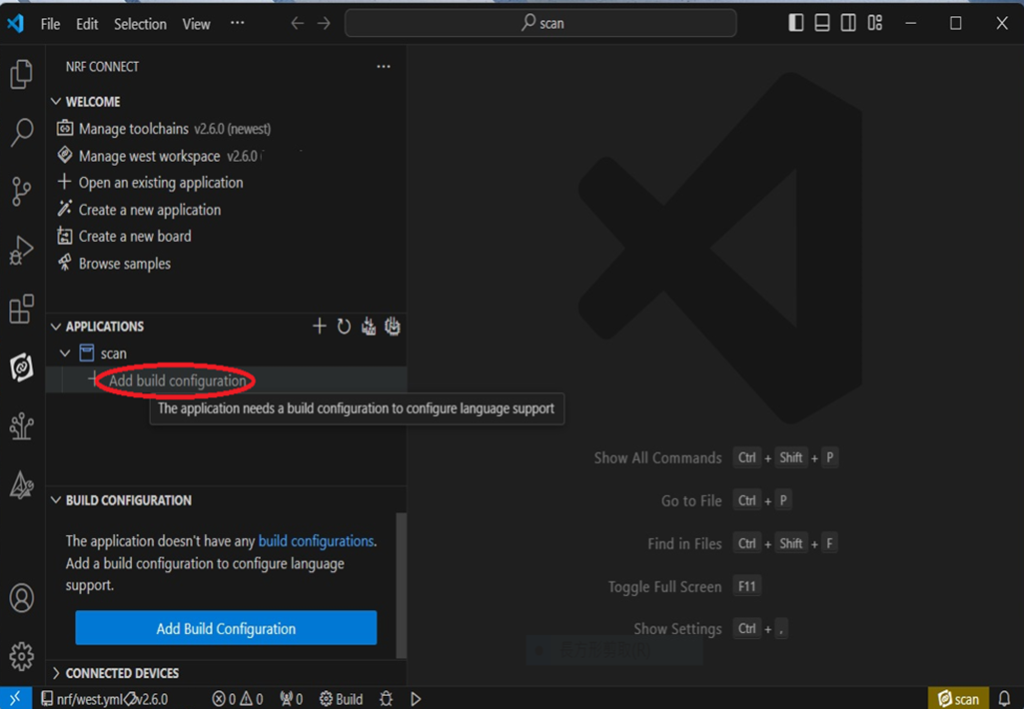
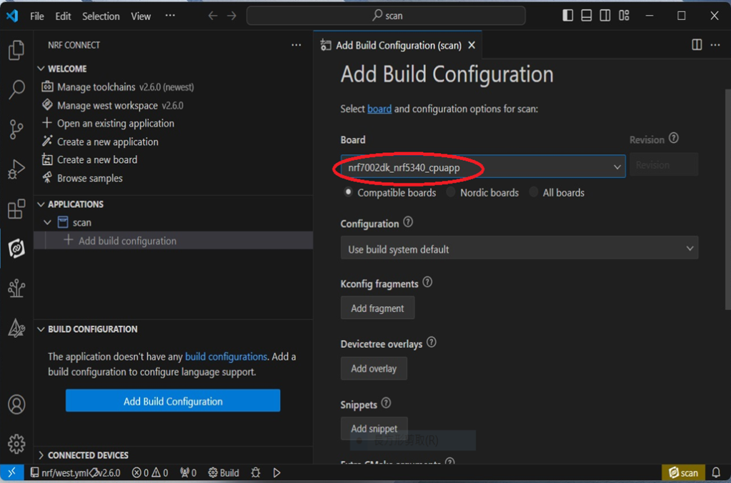
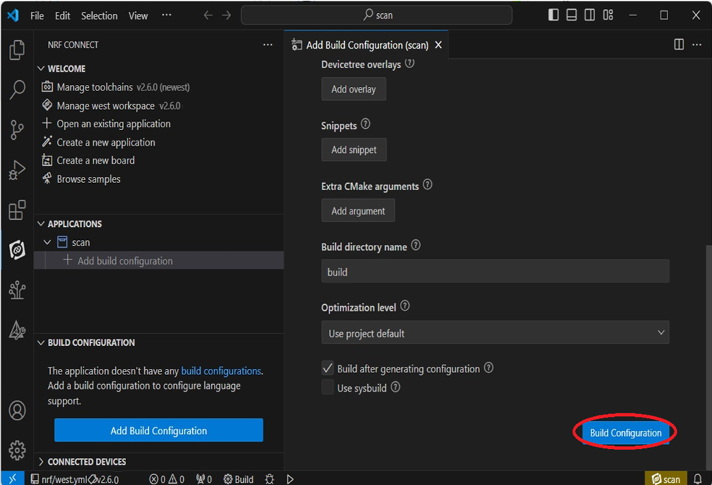
Step 11: Add build configuration.

Step 12: Add build configuration >> Choose Board target: nrf5340dk/nrf5340/cpuapp

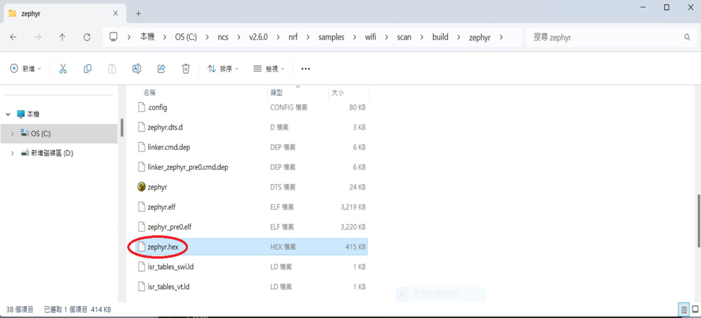
Step 13: Generate and Build

Step 14: Generate a Merged.hex file after compiling the program


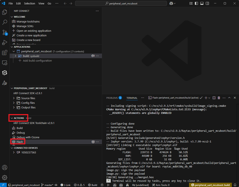
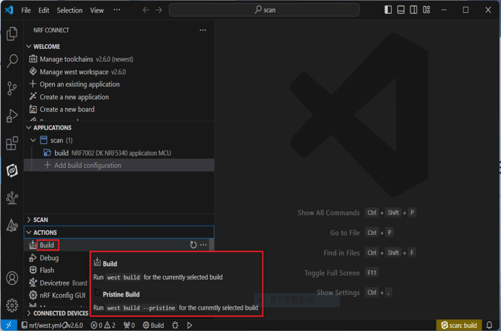
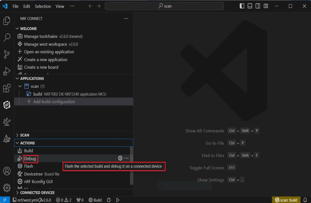
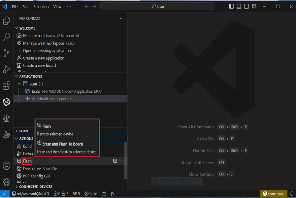
Step15: You can choose Build/Debug/Flash under ACTIONS during development
<< Build >>

<< Debug >>

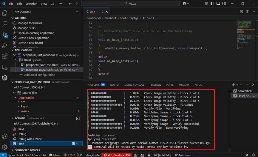
<< Flash >>

Step 16: Go to ACTIONS >> Memory report to check the memory partitions.

Now you can see partitions available in the system.
mcu_secondary has already been located in MX25R64 flash memory.

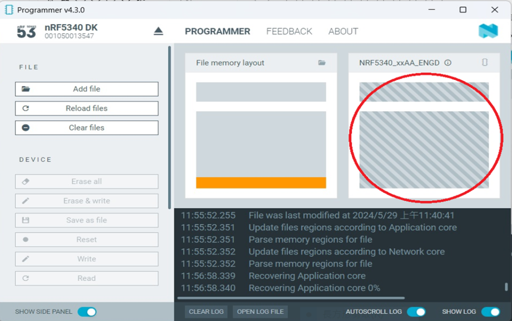
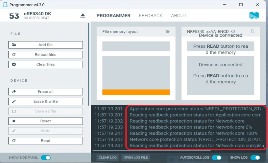
4. Test/Validate DFU Process & WIFI SCAN
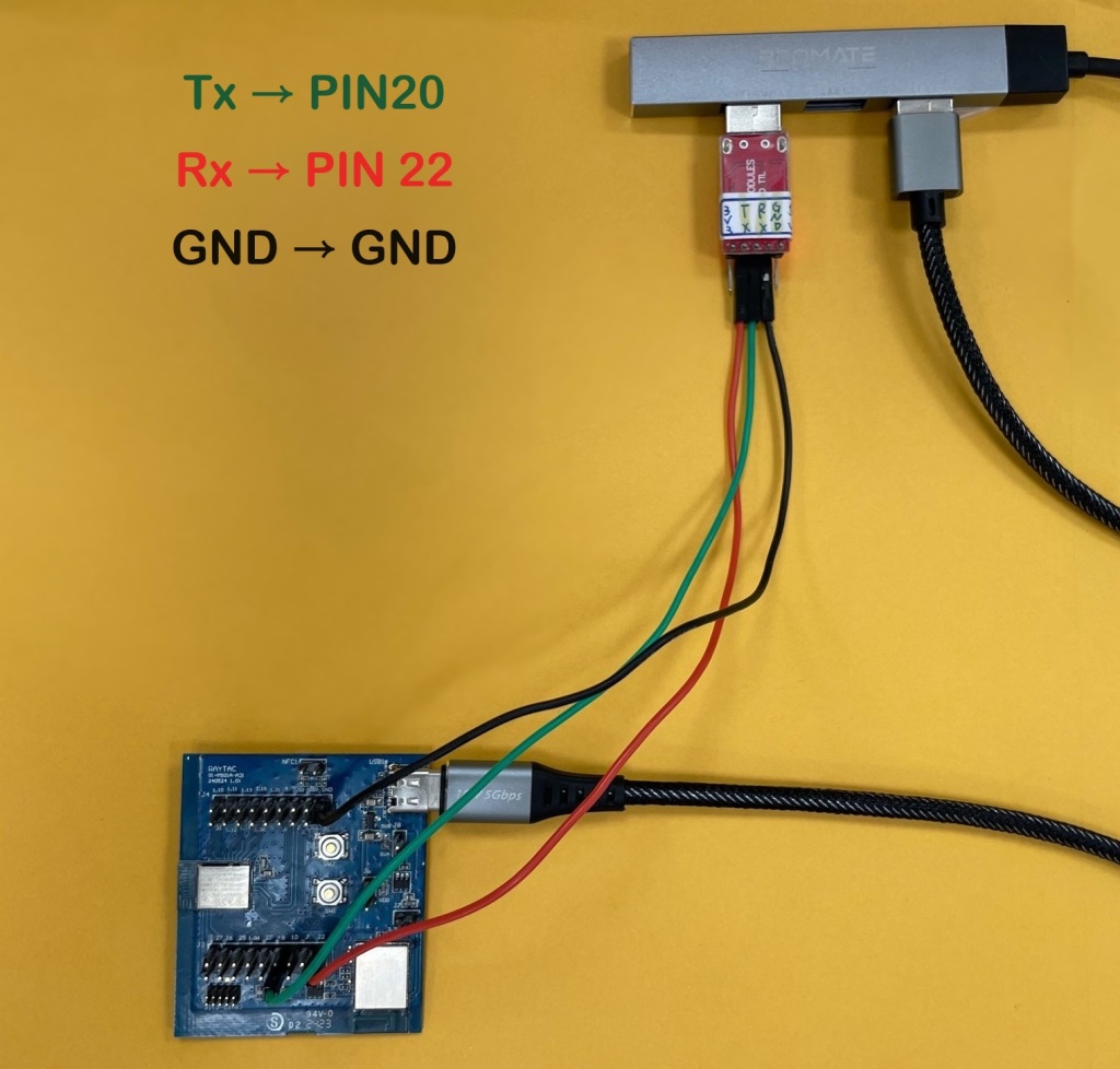
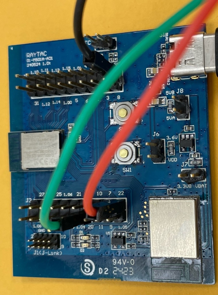
After the firmware programmed to MDBT53 module on board, we use the USB to UART adaptor board for connecting AN7002Q-DB-5340-M through: A. MCUMGR UART to PC and through: B. WiFi Scan UART to PC respectively.
Note: We suggest you finish connecting A. and B. before running tests.


Now we can run the tests.
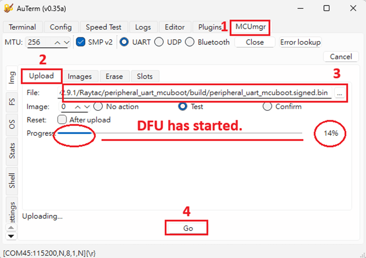
A. DFU over UART – Using AuTerm Program
1. We can locate Image version=V99.0.0 under the current VERSION file

It also indicates Image version: 99.0.0 in MCUmgr-Slot 0.

2. Try to modify the file version from V99 to V100 under VERSION file:
VERSION_MAJOR = 100
VERSION_MINOR = 0
PATCHLEVEL = 0
VERSION_TWEAK = 0
EXTRAVERSION =
And go with “Pristine Build”

3. We’re about to run DFU over UART , Please DO NOT do “Flash” or “Erase”.


Proceed with “Force reboot”

4. It’s now Version 100.0.0 in Slot 0 under MCUgr ⭢ DFU over UART successfully done!

Before it was Version 99.0.0 in Slot 1 under MCUgr.

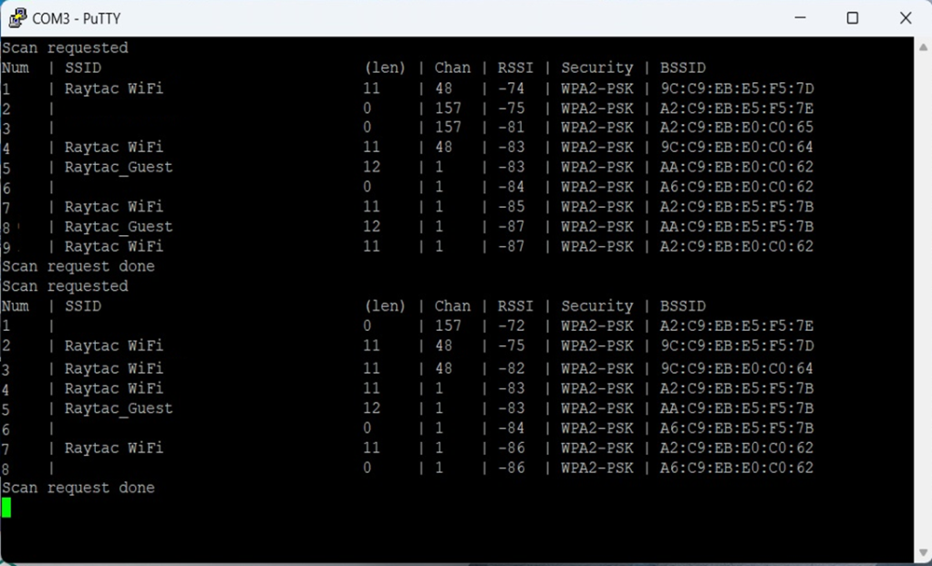
B. WIFI SCAN – PuTTY Console
WIFI SCAN credentials can be located under PC Console – PuTTY.

Useful references:
Nordic Developer Academy
nRF Connect SDK Documentation
Wi-Fi Samples
Nordic DevZone – Technical Forum
Edited by Business Development Manager: Jocelyn Tsai
Technical Guidance by R&D Manager: MW Lee
Raytac Corporation 勁達國際電子股份有限公司 / Raytac Corporation (USA) / abietec Inc.
A Bluetooth, Wi-Fi, and LoRa Module Maker/ODM & OEM Manufacturer based on
Nordic nRF54; nRF53: nRF52; nRF51; nRF7002
Semtech Specification: SX1262
Bluetooth Specification: BT6 ; BT5.4 ; BT5.3 ; BT5.2.
Wi-Fi Specification: Wi-Fi 6
LoRa Specification: LoRaWAN
All products are FCC/IC/CE/Telec/KC/RCM/SRRC/NCC/WPC/RoHS/Reach Pre-Certified.
http://www.raytac.com
https://www.raytac.com/contact/
email: sales@raytac.com
Tel: +886-2-3234-0208(TW)/+1-626-217-3139(USA)